



Contents: Purpose of relays and fuses in the…⤓ Connector markings ⤓ Wire marking ⤓ Color coding ⤓ Abbreviations ⤓
Please note: Only the main wiring harnesses are shown in the illustration.
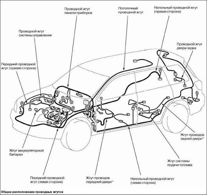
Note: The (*) sign indicates that it is also located on the right side of the vehicle.
Note: The triangular marks on the relay body must match those on the fuse box.
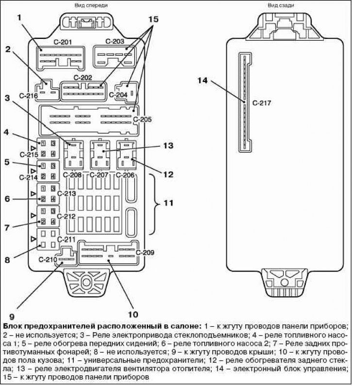
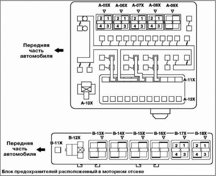
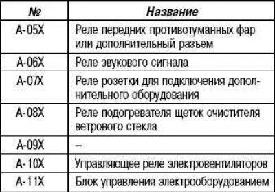
Purpose of relays and fuses in the engine compartment
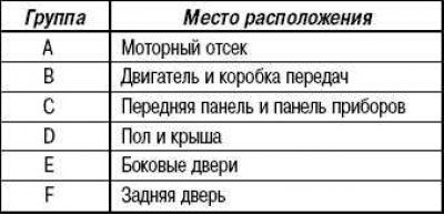
Connector markings
The connectors are divided into groups according to their location on the vehicle and have symbolic designations.
Wire marking
Wires differ in the color of the insulation and the cross-section of the conductive part depending on what electrical devices they are connected to.
The diagrams indicate the wire marking with a letter code.
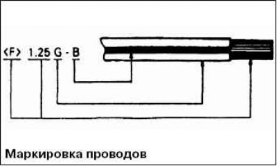
- F – wire type (flexible wire); T: twisted wire.
- 1.25 – wire cross-section in mm. If the value is not specified, the wire cross-section is 0.5 mm. If the wire color code is given in brackets, the wire cross-section is 0.3 mm.
- G – main color of the wire.
- B – additional wire color.
Color coding
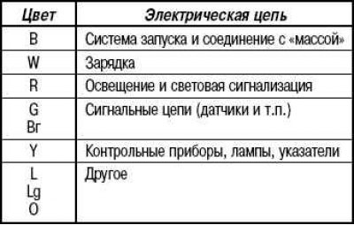
With a two-letter wire insulation color code (for example, RG), the first letter indicates the main color of the wire (red), and the second letter indicates the color of the stripe on the wire (green).
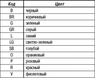
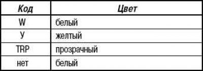
The electrical circuit used depending on the color of the wire insulation
Abbreviations
- J/B: Passenger compartment fuse box.
- J/C: Jumper connector (located on the front panel).
- ACC: The power supply circuit starts to operate when the ignition switch is turned to the "ON" or "ACC" position.
- IG1: The power supply circuit will operate even when the ignition switch is turned to the "ST" position.
- IG2: The power supply circuit does not function when the ignition switch is turned to the "ST" position.
- GND: "mass".
- ILL: backlight lamp.
- IND: indicator lamp.