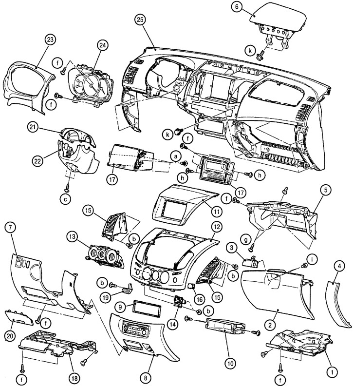
1. Right bottom trim panel; 2. Glove box cover; 3. Glove box lock assembly; 4. Right facing panel; 5. Glove box body; 6. Front passenger airbag; 7. Bottom panel; 8. Central bottom panel; 9. Gasket; 10. Glove box; 11. Upper glove box or display cover; 12. Top center panel; 13. Heater control panel; 14. Emergency stop indicator and switch; 15. Heater nozzle in the central panel; 16. Passenger airbag switch; 17. Upper glove box or display; 18. Left lower facing panel; 19. Bracket of the left lower facing panel; 20. Fuse block; 21. The upper casing of the steering column; 22. The lower casing of the steering column; 23. Casing of a combination of devices; 24. Instrument cluster; 25. Dashboard
a. Self-tapping screw 4x12mm; b. Self-tapping screw 5x12 mm; c. Self-tapping screw 5x16 mm; d. Self-tapping screw 5x10 mm; e. Self-tapping screw 5x12 mm; f. Self-tapping screw 5x16 mm; g. Self-tapping screw 5x16 mm; h. Shoulder screw 5x8 mm; i. Screw with washer 4x12 mm; j. Screw with washer 5x12 mm; k. Bolt with washer 6x16 mm
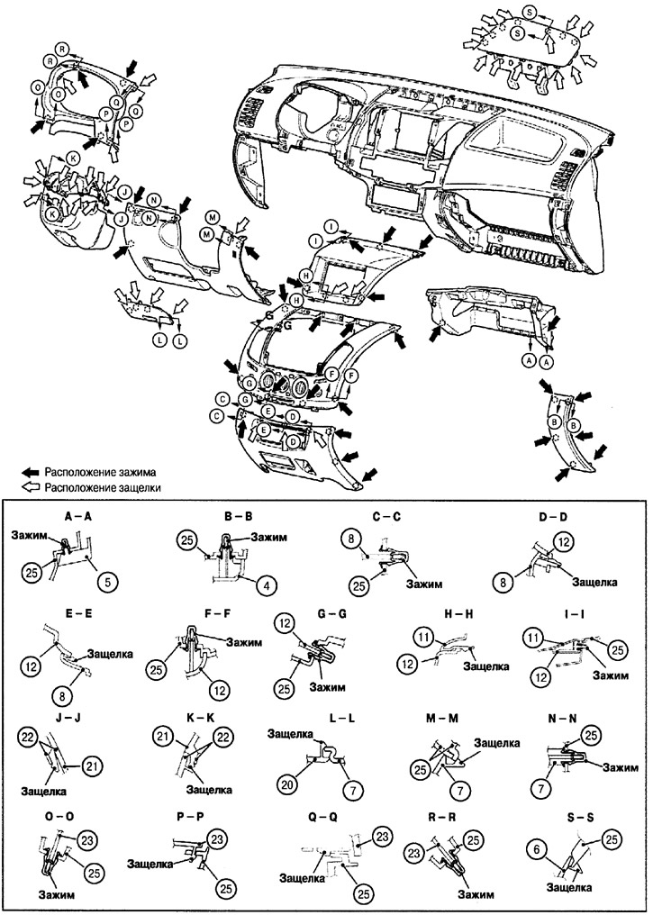
The layout of the clamps and latches on the elements of the instrument panel
(positions indicated by numbers are identical to the positions in the previous figure)