
Share with friends:
Front axle of the car Mitsubishi L200 4

Specifications and design description
The front axle of an all-wheel drive vehicle consists of a main gear mounted in a housing fixed to the body, and drive shafts that transmit rotation to the wheels. The...
The front axle of an all-wheel drive vehicle consists of a main gear mounted in a housing fixed to the body, and drive shafts that transmit rotation to the wheels. The...

Front wheel hub (2WD) — design description
Structural elements of the front axle hub (2WD): 1. Front wheel speed sensor (for vehicles equipped with ABS); 2. Brake caliper; 3. Brake disc; 4. Hub cap; 5. Pin...
Structural elements of the front axle hub (2WD): 1. Front wheel speed sensor (for vehicles equipped with ABS); 2. Brake caliper; 3. Brake disc; 4. Hub cap; 5. Pin...

Front wheel hub (4WD) — design description
Structural elements of the front axle hub (4WD): 1. Front wheel speed sensor (for vehicles equipped with ABS); 2. Brake caliper; 3. Brake disc; 4. Hub cap; 5. Cotter pin...
Structural elements of the front axle hub (4WD): 1. Front wheel speed sensor (for vehicles equipped with ABS); 2. Brake caliper; 3. Brake disc; 4. Hub cap; 5. Cotter pin...

Dismantling the brake disc of the front wheel
The brake disc is attached in the presence of a wheel with wheel nuts. With the wheel removed, the disc is held in place by two screws (M8x1.25 mm). Having unscrewed...
The brake disc is attached in the presence of a wheel with wheel nuts. With the wheel removed, the disc is held in place by two screws (M8x1.25 mm). Having unscrewed...

Front wheel bearing adjustment check
Checking the adjustment of the front wheel hub bearing by measuring the moment of resistance to rotation. Heavily loaded front wheel bearings require a certain preload....
Checking the adjustment of the front wheel hub bearing by measuring the moment of resistance to rotation. Heavily loaded front wheel bearings require a certain preload....

Drive shaft assembly — removal and installation
Structural elements of the front axle hub and drive shaft (4WD): 1. Front wheel speed sensor (for vehicles equipped with ABS); 2. Brake caliper; 3. Brake disc; 4. Hub...
Structural elements of the front axle hub and drive shaft (4WD): 1. Front wheel speed sensor (for vehicles equipped with ABS); 2. Brake caliper; 3. Brake disc; 4. Hub...

Drive shafts — disassembly and assembly
The list of structural elements of the drive shaft to figure M2 5.011: 1. Large clamp (inner CV joint). 2. Small clamp (inner CV joint). 3. Retaining ring. 4. Inner CV...
The list of structural elements of the drive shaft to figure M2 5.011: 1. Large clamp (inner CV joint). 2. Small clamp (inner CV joint). 3. Retaining ring. 4. Inner CV...

Disassembly and assembly of the CV joint
Remove the balls from the cage in the direction shown in fig. M2 5.013. Remove the separator from the inner race. To avoid damage to the boot, cover the spline of the...
Remove the balls from the cage in the direction shown in fig. M2 5.013. Remove the separator from the inner race. To avoid damage to the boot, cover the spline of the...

Inner shaft assembly
Disassembly is carried out in the order indicated in Fig. M2 5.026. Assembly is carried out in the reverse order of disassembly. Dismantling, inner shaft Remove the...
Disassembly is carried out in the order indicated in Fig. M2 5.026. Assembly is carried out in the reverse order of disassembly. Dismantling, inner shaft Remove the...

Differential housing and drive for disabling the right drive shaft from the differential
1. Front flange of the cardan shaft; 2. Self-locking nut (replace with a new one when reassembling); 3. Bolt of fastening of a back traverse of a forward suspension...
1. Front flange of the cardan shaft; 2. Self-locking nut (replace with a new one when reassembling); 3. Bolt of fastening of a back traverse of a forward suspension...

Disassembly and assembly of the mechanism for disconnecting the right drive shaft from the differential
Disassembly is carried out in the order indicated in Fig. M2 5.036. Assembly is carried out in the reverse order of disassembly. Installation of an intermediate ring...
Disassembly is carried out in the order indicated in Fig. M2 5.036. Assembly is carried out in the reverse order of disassembly. Installation of an intermediate ring...

Front axle differential, assy
Differential design elements: 1. Filler plug; 2. Gasket (replace with a new one when reassembling); 3. Drain plug; 4. Seal (replace with a new one when reassembling); 5....
Differential design elements: 1. Filler plug; 2. Gasket (replace with a new one when reassembling); 3. Drain plug; 4. Seal (replace with a new one when reassembling); 5....
Solenoid valve and vacuum hose
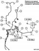
Design elements of the solenoid valve and vacuum pipeline: 1. Solenoid valve connector; 2. Solenoid valve assembly; 3. Vacuum hose; 4. Vacuum tank; 5. Vacuum pipeline...
Design elements of the solenoid valve and vacuum pipeline: 1. Solenoid valve connector; 2. Solenoid valve assembly; 3. Vacuum hose; 4. Vacuum tank; 5. Vacuum pipeline...

Removal and installation of front axle differential
Set of fastening elements for front axle differential: 1. Differential mounting bracket assembly (LH); 2. Differential mounting bracket assembly (RH); 3. Rear cross beam...
Set of fastening elements for front axle differential: 1. Differential mounting bracket assembly (LH); 2. Differential mounting bracket assembly (RH); 3. Rear cross beam...
This section is available on: russian, bulgarian, belarusian, ukrainian, serbian, croatian, romanian, polish, slovak, hungarian
Link in different formats to this section
TEXTHTMLBB Code
- General information
- User manual
- Maintenance
- Power unit
- Diesel engine
- Lubrication system
- Fuel system
- Control system
- Transmission
- Clutch
- Mechanical gearbox
- Transfer case
- Front axle
- Rear axle
- Chassis and running gear
- Car suspension
- Steering
- Brake system
- Body and interior
- Exterior (external elements)
- Interior (internal elements)
- Doors, locks and windows
- Electrical equipment
- Equipment and devices
- Electrical circuits
MitsubishiMan.ru © 2018–2024 • Mobile version • Articles about Mitsubishi • Contacts • Sitemap: EN BG BY UA RS HR RO PL SK HU • Site search • Bookmark
Colt 2 and 3 (1983-1993) · Colt 4 and 5 (1991-2003) · Colt 5 (1995-2003) · Lancer 3 and 5 (1984-1992) · Lancer 9 (2000-2007) · Galant 6 and 7 (1987-1998) · L200 4 (2005-2014) · Outlander 1 (2003-2008) · Pajero 1 and 2 (1982-1999) · Carisma (1995-2004) · Space Star (1998-2005) ·
Colt 2 and 3 (1983-1993) · Colt 4 and 5 (1991-2003) · Colt 5 (1995-2003) · Lancer 3 and 5 (1984-1992) · Lancer 9 (2000-2007) · Galant 6 and 7 (1987-1998) · L200 4 (2005-2014) · Outlander 1 (2003-2008) · Pajero 1 and 2 (1982-1999) · Carisma (1995-2004) · Space Star (1998-2005) ·