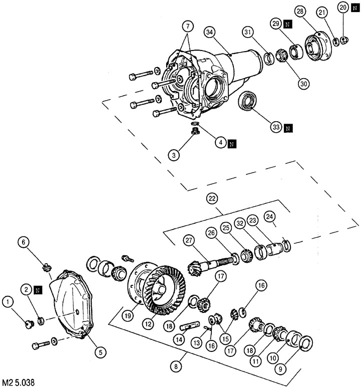
Differential design elements: 1. Filler plug; 2. Gasket (replace with a new one when reassembling); 3. Drain plug; 4. Seal (replace with a new one when reassembling); 5. Differential cover; 6. Vent plug (for vehicles equipped with Easy select 4WD); 7. Bearing caps; 8. Differential housing assembly; 9. Intermediate adjusting ring of the differential side bearing; 10. External race of the lateral bearing of differential; 11. The inner race of the differential side bearing; 12. Driven gear of the final drive; 13. Locking pin; 14. Satellite shaft; 15. Satellite; 16. Satellite washer; 17. Axle gear; 18. Intermediate adjusting ring of the axle shaft gear; 19. Differential housing; 20. Self-locking nut (replace with a new one when reassembling); 21. Washer; 22. Drive shaft final drive gear assembly; 23. Intermediate ring of the main gear drive shaft; 24. Front adjusting washer of the main gear drive shaft; 25. The inner race of the rear bearing of the main gear drive shaft; 26. Rear adjusting washer of the main gear drive shaft; 27. Main gear drive shaft; 28. Connecting flange; 29. Oil seal (replace with a new one when reassembling); 30. The inner race of the front bearing of the main gear drive shaft; 31. The outer race of the front bearing of the main gear drive shaft; 32. External cage of the rear bearing of the main gear drive shaft; 33. Oil seal (replace the assembly with a new one); 34. Differential housing
Dismantling of nalkzaldittya in the order specified in fig. M2 5.038. Assembly is carried out in the reverse order of disassembly.
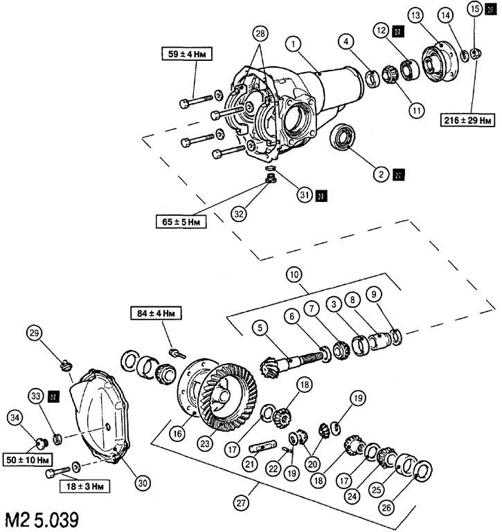
Differential design elements: 1. Differential housing; 2. Oil seal (replace with a new one when reassembling); 3. Outer race of the rear bearing of the main gear drive shaft; 4. The outer race of the front bearing of the main gear drive shaft; 5. Main gear drive shaft; 6. Rear adjusting washer of the main gear drive shaft; 7. The inner race of the rear bearing of the main gear drive shaft; 8. Intermediate ring of the main gear drive shaft; 9. Front adjusting washer of the main gear drive shaft; 10. Drive shaft final drive gear assembly; 11. The inner race of the front bearing of the main gear drive shaft; 12. Oil seal (replace with a new one when reassembling); 13. Connecting flange; 14. Washer; 15. Self-locking nut (replace with a new one when reassembling); 16. Differential housing; 17. Intermediate adjusting ring of the axle shaft gear; 18. Axle gear; 19. Satellite washer; 20. Satellite; 21. Satellite shaft; 22. Locking pin; 23. Driven gear of the main gear; 24. The inner race of the differential side bearing; 25. External race of the side differential bearing; 26. Intermediate adjusting ring of the differential side bearing; 27. Differential housing assembly; 28. Bearing caps; 29. Vent plug (for vehicles equipped with Easy select 4WD); 30. Differential cover; 31. Seal (replace with a new one when reassembling); 32. Drain plug; 33. Gasket (replace with a new one when reassembling); 34. Filler plug
Assembly is carried out in the order shown in Fig. M2 5.039.
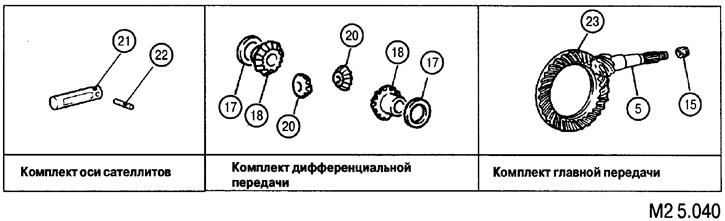
5. Main gear drive shaft; 15. Self-locking nut (replace with a new one when reassembling); 17. Intermediate adjusting ring of the axle shaft gear; 18. Axle gear; 20. Satellite; 21. Satellite shaft; 22. Locking pin; 23. Main gear driven
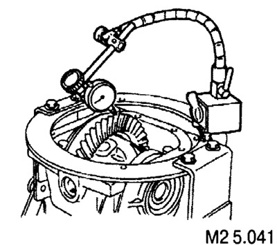
Measuring the backlash in the gearing of the final drive
The gear gap is measured with a suitable measuring device (such as shown in Fig. M2 5.041). The gap should be between 0.11 and 0.16 mm.
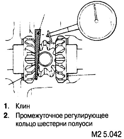
Measuring wear in the gearing of the pinion gears and side gears of the differential gear
Measure the backlash between the planet gears and the side gears with a suitable measuring device, having previously fixed the axle gear with a wedge (see fig. M2 5.042). The gap should be between 0.01 and 0.250 mm.