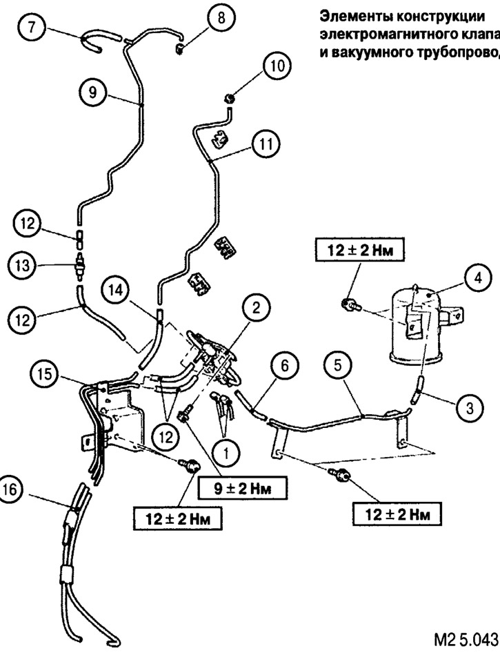
Design elements of the solenoid valve and vacuum pipeline: 1. Solenoid valve connector; 2. Solenoid valve assembly; 3. Vacuum hose; 4. Vacuum tank; 5. Vacuum pipeline assembly; 6. Vacuum hose; 7. Vacuum hose; 8. Vacuum valve cover; 9. Vacuum hose; 10. Breather cap; 11. Vacuum pipeline; 12. Vacuum hose; 13. Control valve; 14. Vacuum hose; 15. Vacuum pipeline assembly; 16. Vacuum hose assembly
Removal of the electromagnetic valve is made in the following order: 1.2.
Removal of the vacuum tank, vacuum hoses and vacuum pipeline is carried out in the following order: 3, 4, 5, 6, 7, 8, 9, 10, 11, 12, 13, 14, 15, 16.
Installation of vacuum hoses and tubes
When installing vacuum hoses and tubes, observe the color coding (see fig. M2 5.044).
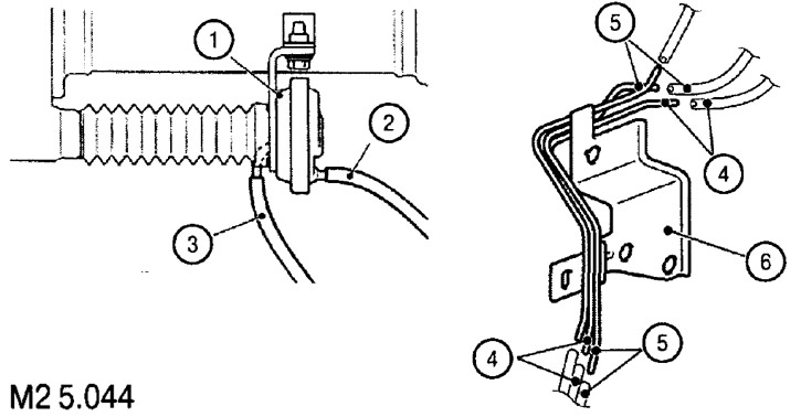
1. The drive for disabling the right drive shaft from the differential; 2. Blue hose; 3. Yellow hose; 4. Vacuum chamber; 5. Blue color coding with stripe; 6. Yellow color coding with stripe
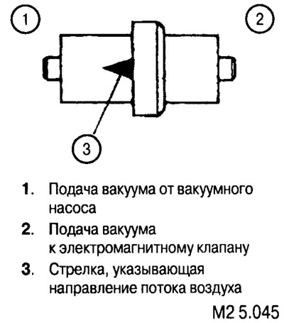
Check valve installation
After installation, the arrow indicating the direction of air must be turned towards the vacuum source (ss. pic. M2 5.045).