
Share with friends:
Car transfer case Mitsubishi L200 4

4WD Easy select drive system — description and principle of operation
In the transfer case, the 2WD/4WD shift mechanism is a 2-bevel synchronizer. This makes it possible to switch between 2WD/4WD modes while driving and reduces shifting...
In the transfer case, the 2WD/4WD shift mechanism is a 2-bevel synchronizer. This makes it possible to switch between 2WD/4WD modes while driving and reduces shifting...

Design and operation of the 2WD / 4WD shift mechanism
The engagement of the front axle drive occurs when the movable spline ring of the coupling engages with the ring gear of the drive pulley of the front axle drive gear...
The engagement of the front axle drive occurs when the movable spline ring of the coupling engages with the ring gear of the drive pulley of the front axle drive gear...

Drive system 4WD Super select — description and principle of operation
Unlike the system described in the previous section, the Super select system is supplemented by a center differential and a viscous coupling installed in the transfer...
Unlike the system described in the previous section, the Super select system is supplemented by a center differential and a viscous coupling installed in the transfer...

2WD/4WD Mode Switching Mechanism
1. Transfer case drive shaft; 2. Differential lock hub; 3. Clutch hub of the synchronizer of the 2WD / 4WD shift mechanism; 4. Movable splined ring of the 2WD / 4WD...
1. Transfer case drive shaft; 2. Differential lock hub; 3. Clutch hub of the synchronizer of the 2WD / 4WD shift mechanism; 4. Movable splined ring of the 2WD / 4WD...

Removal and installation of cardan shafts
Set the transfer case control lever to the position «2H». Drain the oil from the transfer case. Apply alignment marks. The sequence of removal of cardan shafts: 1....
Set the transfer case control lever to the position «2H». Drain the oil from the transfer case. Apply alignment marks. The sequence of removal of cardan shafts: 1....

Disassembly and assembly of cardan shafts
Removing needle bearings Removal of needle bearings is carried out using a press and mandrels. At the same time, the opposite cup of the needle bearing race is pressed...
Removing needle bearings Removal of needle bearings is carried out using a press and mandrels. At the same time, the opposite cup of the needle bearing race is pressed...

Easy select transfer case disassembly sequence
All-wheel drive transfer box Easy select (used in conjunction with manual transmission type V5MB1-J-NEG) Easy select transfer case disassembly sequence (see fig. M2...
All-wheel drive transfer box Easy select (used in conjunction with manual transmission type V5MB1-J-NEG) Easy select transfer case disassembly sequence (see fig. M2...

Super select transfer case disassembly sequence
Super select all-wheel drive transfer box (used in conjunction with manual transmission type V5MB1-J-NE) Super select transfer case disassembly sequence (see fig. M2...
Super select all-wheel drive transfer box (used in conjunction with manual transmission type V5MB1-J-NE) Super select transfer case disassembly sequence (see fig. M2...

Removing the shift rod
1. Lock the shift rod (increased or decreased (H-L)) in the overdrive position. 2. Switch to 4WD mode. Attention: if the 2WD mode was enabled during disassembly, then...
1. Lock the shift rod (increased or decreased (H-L)) in the overdrive position. 2. Switch to 4WD mode. Attention: if the 2WD mode was enabled during disassembly, then...

Adjustments before assembly
The measurement is made using pieces of wire made of soft solder (diameter: 1.0mm, length: about 10mm). For this crumpled pieces of wire (further - calibers) should be...
The measurement is made using pieces of wire made of soft solder (diameter: 1.0mm, length: about 10mm). For this crumpled pieces of wire (further - calibers) should be...

Installation of oil seals
The seals are installed using appropriately sized mandrels. Installation of rear axle drive output shaft, front axle drive chain, front axle drive output shaft....
The seals are installed using appropriately sized mandrels. Installation of rear axle drive output shaft, front axle drive chain, front axle drive output shaft....

Transfer case assembly sequence
Installing the Shift Synchronizer Hub (H-L) When installing the hub, pay attention to its installation position (see fig. M2 4.081). Installing retaining rings Before...
Installing the Shift Synchronizer Hub (H-L) When installing the hub, pay attention to its installation position (see fig. M2 4.081). Installing retaining rings Before...

Installation of limit switches — position sensors of parts of the transfer mechanism
Functions of sensors - limit switches and their correspondence to connectors Designation The content of information coming from the sensor Connector number Connector...
Functions of sensors - limit switches and their correspondence to connectors Designation The content of information coming from the sensor Connector number Connector...

Removal and installation of the drive gear transfer case Easy Select
Disassembly sequence: 1. Screw; 2. clamping bracket of the bearing; 3. Transfer case drive gear; 4. Oil seal; 5. Oil deflector; 6. Sealant; 7. Transfer box front cover...
Disassembly sequence: 1. Screw; 2. clamping bracket of the bearing; 3. Transfer case drive gear; 4. Oil seal; 5. Oil deflector; 6. Sealant; 7. Transfer box front cover...

Dismantling and assembly of the synchronizer of inclusion of the forward drive of a razdatki Super select
Disassembly sequence: 1. Retaining ring; 2. Synchronizer hub 2WD - 4WD; 3. Synchronizer spring; 4. External blocking ring of the synchronizer; 5. Two-conical ring; 6....
Disassembly sequence: 1. Retaining ring; 2. Synchronizer hub 2WD - 4WD; 3. Synchronizer spring; 4. External blocking ring of the synchronizer; 5. Two-conical ring; 6....
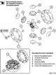
Dismantling and assembling the mechanism of the center differential of the transfer case Super select
Before dismantling, mark the relative position of the housing halves, as well as the internal parts of the differential. Disassembly sequence: 1. Body (A) differential;...
Before dismantling, mark the relative position of the housing halves, as well as the internal parts of the differential. Disassembly sequence: 1. Body (A) differential;...

Disassembly and assembly of the shift fork
Disassembly sequence: 1. Plug return spring; 2. Return spring; 3. Return spring; 4. Piston selection mechanism; 5. Piston sleeve; 6. shift fork
Disassembly sequence: 1. Plug return spring; 2. Return spring; 3. Return spring; 4. Piston selection mechanism; 5. Piston sleeve; 6. shift fork

Dismantling and assembling the output shaft of the drive of the rear place of the transfer case Easy select
Disassembly sequence: 1. Locknut; 2. Ball bearing; 3. Oil guide impeller; 4. Adjusting washer of the position of the drive toothed pulley of the chain drive; 5. Steel...
Disassembly sequence: 1. Locknut; 2. Ball bearing; 3. Oil guide impeller; 4. Adjusting washer of the position of the drive toothed pulley of the chain drive; 5. Steel...

Dismantling and assembling the output shaft of the rear axle drive of the Super select transfer case
Disassembly sequence: 1. Retaining ring; 2. Ball bearing; 3. Viscous coupling; 4. Rear axle output shaft Dismantling and assembly of an output shaft of a drive of the...
Disassembly sequence: 1. Retaining ring; 2. Ball bearing; 3. Viscous coupling; 4. Rear axle output shaft Dismantling and assembly of an output shaft of a drive of the...

Transfer case adjustment parameters
Parameter Normal value Limit value Axial run of the intermediate shaft 0-0.15mm - Axial run of the hub of the gearshift clutch (increased or decreased) 0-0.08mm - Axial...
Parameter Normal value Limit value Axial run of the intermediate shaft 0-0.15mm - Axial run of the hub of the gearshift clutch (increased or decreased) 0-0.08mm - Axial...
This section is available on: russian, bulgarian, belarusian, ukrainian, serbian, croatian, romanian, polish, slovak, hungarian
Link in different formats to this section
TEXTHTMLBB Code
- General information
- User manual
- Maintenance
- Power unit
- Diesel engine
- Lubrication system
- Fuel system
- Control system
- Transmission
- Clutch
- Mechanical gearbox
- Transfer case
- Front axle
- Rear axle
- Chassis and running gear
- Car suspension
- Steering
- Brake system
- Body and interior
- Exterior (external elements)
- Interior (internal elements)
- Doors, locks and windows
- Electrical equipment
- Equipment and devices
- Electrical circuits
MitsubishiMan.ru © 2018–2024 • Mobile version • Articles about Mitsubishi • Contacts • Sitemap: EN BG BY UA RS HR RO PL SK HU • Site search • Bookmark
Colt 2 and 3 (1983-1993) · Colt 4 and 5 (1991-2003) · Colt 5 (1995-2003) · Lancer 3 and 5 (1984-1992) · Lancer 9 (2000-2007) · Galant 6 and 7 (1987-1998) · L200 4 (2005-2014) · Outlander 1 (2003-2008) · Pajero 1 and 2 (1982-1999) · Carisma (1995-2004) · Space Star (1998-2005) ·
Colt 2 and 3 (1983-1993) · Colt 4 and 5 (1991-2003) · Colt 5 (1995-2003) · Lancer 3 and 5 (1984-1992) · Lancer 9 (2000-2007) · Galant 6 and 7 (1987-1998) · L200 4 (2005-2014) · Outlander 1 (2003-2008) · Pajero 1 and 2 (1982-1999) · Carisma (1995-2004) · Space Star (1998-2005) ·