English Русский
Български
Беларускі
Український
Српски
Hrvatski
Română
Polski
Slovenský
Magyar
Articles Bookmark Contacts Sitemap   
Company Audi Company Ford Company Hyundai Company Kia Company Mazda Company Mercedes-Benz Company Nissan
MitsubishiMan.ru


Home Colt Lancer Galant L200 Outlander Pajero Others
L200 4 (2005-2014, diesel)

Disassembly and assembly of cardan shafts (Mitsubishi L200 4)

  • Home
  • L200
  • 4 (2005-2014, diesel)
  • Transmission
  • Transfer case
  • Disassembly and assembly of cardan shafts
0
Contents: Removal needle bearings ⤓ Splined connections ⤓ Removal the hanger bearing ⤓ Assembly of the hanger bearing ⤓ Assembly of cardan joints ⤓ Installing retaining rings ⤓

Removal needle bearings


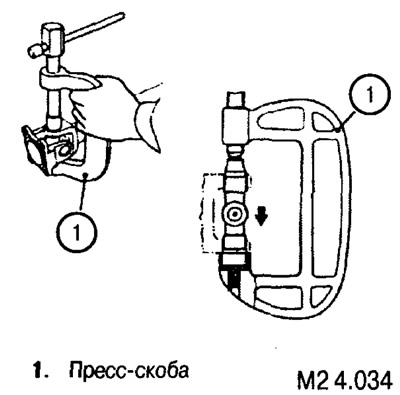
Needle bearings are removed using a press and mandrels. The pressure mandrel presses out the opposite cup of the needle bearing cage, which passes into the hole of the opposite mandrel.


Splined connections


Before separating the splined connections, apply alignment marks as shown in fig. M2 4.032.

The article is based on data from the website MITSUBISHIMAN

Removal the hanger bearing


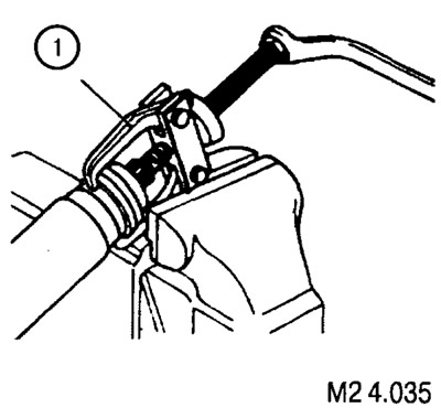
The suspension bearing is removed using a universal puller (1).


Assembly of the hanger bearing
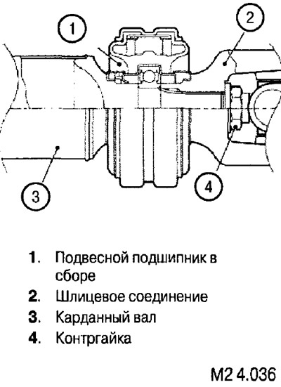


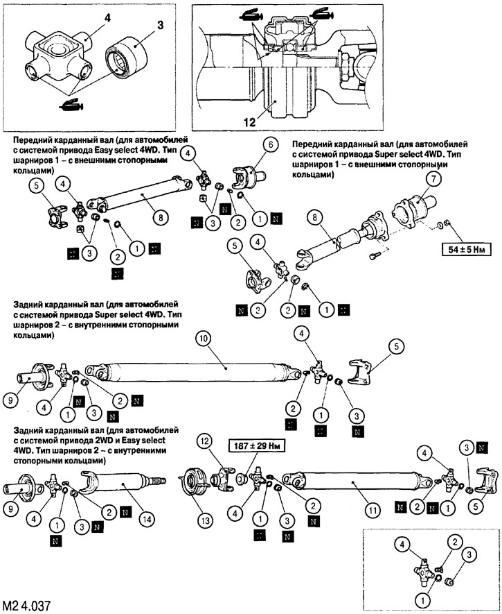
Disassembly sequence: 1. Retaining ring; 2. Butter dish; 3. Needle bearings; 4. Crosspiece with needle bearing journals; 5. Cardan joint flange; 6. Splined sleeve with cardan joint fork (for vehicles with Easy select 4WD drive system. Joint type 1 - with external retaining rings); 7. Splined sleeve with cardan joint fork (for vehicles with Super select 4WD drive system, joint type 1 - with external retaining rings); 8. Front propeller shaft (for vehicles with Easy select 4WD drive system); 9. Splined sleeve with cardan joint fork; 10. Rear propeller shaft (for vehicles with Super select 4WD drive system. Joint type 2 - with internal locking rings); 11 Rear propeller shaft (for vehicles with 2WD and Easy select 4WD drive systems. Joint type 2 - with internal locking rings); 12. Splined sleeve with cardan joint fork; 13. Suspension (intermediate) bearing assembly; 14. Front propeller shaft (for vehicles with 2WD and Easy select 4WD drive systems. Joint type 2 - with internal locking rings)


Assembly of cardan joints


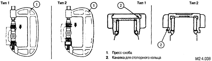
To install the retaining rings of the needle bearing cups, carefully compress them using a press.


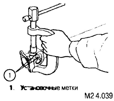
3. Align the timing marks (1) (see Fig. M2 4.039) and install the needle bearing cups.


Installing retaining rings
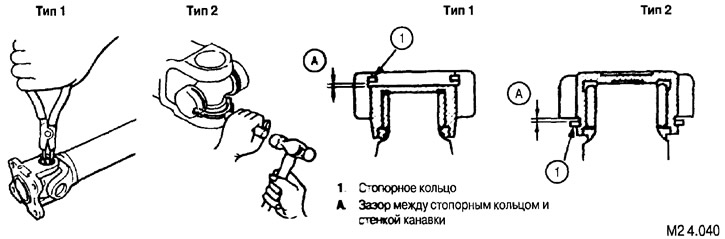


Use retaining rings of equal thickness on opposite sides of the crosspiece.


When installing the retaining rings, measure the gap (A) between the rings and the groove walls. The gap should be no more than 0.06 mm.

If the gap is greater than specified, select retaining rings of appropriate thickness.

Type 1 Retaining Ring ThicknessType 2 Retaining Ring ThicknessColor coding
1,281,50
1,311,55Yellow
1,341,60Blue
1,371,65Purple
1,401,75Brown
1,80Grey
1,85Brown
1,90Blue
This article is available at: russian, bulgarian, belarusian, ukrainian, serbian, croatian, romanian, polish, slovak, hungarian
This article was reviewed by: Nikita Romanov
Share with friends:
◀ Previous
L200 4: Transfer case
Next ▶

Removal and installation of cardan shafts
2WD/4WD mode switching mechanism
4WD Super select drive system — description and operating principle
Design and operating principle of the 2WD/4WD switching mechanism
4WD Easy select drive system — description and operating principle
Easy select transfer case disassembly sequence
Super select transfer case disassembly sequence
Removal the gear shift rod
Adjustments before assembly
Installation of seals
Similar materials for other Mitsubishi models

➤ Disassembly and assembly of automatic transmission Mitsubishi Colt 4 and 5 (1991-2003)
➤ Checking the rubber seals of the drive shafts Mitsubishi Lancer 3 and 5 (1984-1992)
➤ Checking the condition of the protective covers of the… Mitsubishi Galant 6 and 7 (1987-1998)
➤ Disassembly and assembly of the cardan shaft Mitsubishi Outlander 1 (2003-2008)
➤ Valves and rocker shafts — disassembly Mitsubishi Pajero 1 and 2 (1982-1999)
➤ Disassembly and assembly of the throttle assembly Mitsubishi Carisma (1995-2004)
Link in different formats to this article
Comments and feedback from visitors
No comments yet


Add up two numbers 13 + 22


L200 4 (2005-2014, diesel) 
  • General information
  • User manual
  • Maintenance
  • Power unit
  • Diesel engine
  • Lubrication system
  • Fuel system
  • Control system
  • Transmission
  • Clutch
  • Mechanical gearbox
  • Transfer case
  • Front axle
  • Rear axle
  • Chassis and running gear
  • Car suspension
  • Steering
  • Brake system
  • Body and interior
  • Exterior (external elements)
  • Interior (internal elements)
  • Doors, locks and windows
  • Electrical equipment
  • Equipment and devices
  • Electrical circuits
MitsubishiMan.ru © 2018–2026 • Mobile version • Articles about Mitsubishi • Contacts • Sitemap: EN BG BY UA RS HR RO PL SK HU • Site search • Bookmark
Colt 2 and 3 (1983-1993) · Colt 4 and 5 (1991-2003) · Colt 5 (1995-2003) · Lancer 3 and 5 (1984-1992) · Lancer 9 (2000-2007) · Galant 5 (1983-1989) · Galant 6 and 7 (1987-1998) · L200 4 (2005-2014) · Outlander 1 (2003-2008) · Pajero 1 and 2 (1982-1999) · Pajero 4 (2006-2021) · Carisma (1995-2004) · Space Star (1998-2005) ·
This resource sets cookies 🍪 to avoid bothering you with repeated data entry.