
Attention! Do not disassemble the CV joint «Bierfeld» (B.J.), except when replacing the protective cover (supplied in repair kit) SHRUS «Bierfeld» (B.J.).
Attention! Be careful not to damage the rotor mounted on the outer race of the CV joint «Bierfeld» (B.J.).
Drive shaft with roller joint
Before replacing the hinge boot, you should measure the distance between the collars of the boot, since when installing new boots, this distance must be maintained in order to avoid premature wear of the boot.
Disassembly
1. Remove the drive shaft.
2. When replacing the hinge, it is necessary to determine its number, which is available on the cover or on the cover collar.
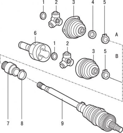
Pic. 15.19. Drive shaft: A - left side (vehicles with 1600 cc engines3 and 1900D with manual transmission); B - right side (vehicles with 1600 cc engines3 and 1900D with manual transmission and 1600 and 1800 cc3 with automatic transmission); 1 - retaining ring; 2 - the inner clip of the CV joint «tripod» (T.J.) complete with spherical rollers; 3 - CV joint case «tripod» (T.J.); 4 - anther; 5 - CV joint clamp «tripod» (T.J.); 6 - CV joint housing «tripod» (T.J.); 7 - dynamic damper (for models with 1600 and 1800 cc petrol engines3); 8 - damper collar (for models with 1600 and 1800 cc petrol engines3); 9 - SHRUS «Bierfeld» (B.J.) complete
3. Remove housing 6 (pic. 15.19) SHRUS «tripod» (T.J.).
4. Remove retaining ring 1. Remove grease from CV joint parts and use paint or chalk to mark alignment on drive shaft and inner race.
5. Fix the rollers of the hinge with adhesive tape, then remove the inner clip of the CV joint «tripod» (T.J.) complete with spherical rollers.
6. Remove the clamp 5 fastening the protective cover of the CV joint drive shaft «tripod» (T.J.).
7. Remove boot 4.
8. Remove the protective cover 3 SHRUS «tripod» (T.J.).
Attention! 9. Remove clamp 8 damper mounting (for models with 1600 and 1800 cc petrol engines3).
Attention! 10. Remove dynamic damper 7 (for models with 1600 and 1800 cc petrol engines3).
11. Remove the CV joint «Bierfeld» (B.J.) assembled.
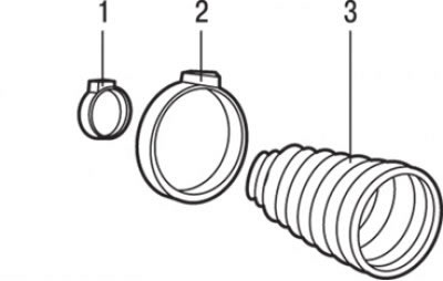
Pic. 15.20. CV joint repair kit «Bierfeld» (B.J.): 1 - a small clamp for fastening the CV joint cover «Bierfeld» (B.J.); 2 - a large clamp for fastening the CV joint cover «Bierfeld» (B.J.); 3 - CV joint cover «Bierfeld» (B.J.)
12. Remove the small collar 1 (pic. 15.20) fastening of the CV joint cover «Bierfeld» (B.J.).
13. Remove the large collar 2 fastenings of the SHRUS cover «Bierfeld» (B.J.).
14. Remove the protective cover 3 SHRUS «Bierfeld» (B.J.). If the boot is to be reinstalled, wrap the shaft splines with adhesive tape before removing the boot.
Examination
1. Thoroughly wash all parts of the hinge with solvent until the old hinge grease is completely removed.
2. Check all hinge parts for cracks, gouges, nicks, pitting, and uneven wear.
Assembly
1. Wrap the splines of the drive shaft with adhesive tape and slide a new protective boot over the drive shaft. Remove adhesive tape.
2. Install the inner CV joint «tripod» (T.J.) with spherical rollers assemblies, while the previously applied marks on the hinge and shaft must be aligned.
3. Install retaining ring.
4. If the rollers were removed from the inner race, coat the roller bearings with a layer of grease and install the rollers on the axles of the inner race.
5. Apply half of the required amount of grease to the inner pivot housing and inner race. When installing the hinge housing, check that the alignment marks made when removing the housing match.
6. Install the protective cover and secure it with clamps.
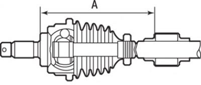
Pic. 15.21. Distance (A) installation of a dynamic damper on the drive shaft: for models with 1600 cc petrol engine3 (with MCP) – left drive shaft A= (264±3) mm, right drive shaft A= (369±3) mm; for models with 1600 petrol engines (AKP) and 1800 cm3 – left drive shaft A= (191±3) mm, right drive shaft A= (371±3) mm
Attention! 7. Install a dynamic damper (for models with 1600 and 1800 cc petrol engines3) or damper clamp (for models with 1600 and 1800 cc petrol engines3). Install the dynamic damper as shown in fig. 15.21.
8. Install the drive shaft.
Drive shaft with ball joint and cage
Attention! On vehicles with F9Q engines and a ball joint and cage, special care must be taken when removing and installing the drive shaft so as not to damage the wheel speed sensor rotors mounted on the outer CV joint housings «Rzeppa».
On vehicles with F9Q engines and internal ball joint and cage, external constant velocity joint «Rzeppa» (R.J.) cannot be disassembled.
On vehicles with F9Q engines, first remove the brake hose clamp, disconnect the speedometer drive cable, disconnect the anti-roll bar and remove the side lower cover.
Disassembly
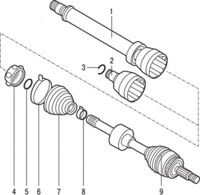
Pic. 15.22. Drive shaft with ball joint and cage, installed on vehicles with F9Q engines: 1 - CV joint housing «tripod» (T.J.) right wheel drive assembly; 2 - CV joint housing «tripod» (T.J.) left wheel drive; 3 - retaining ring (left wheel drive shaft); 4 - hinge assembly; 5 - retaining ring; 6 - a large collar of the CV joint cover «tripod» (T.J.); 7 - protective cover of the CV joint «tripod» (T.J.); 8 – a small collar of a cover of SHRUS «tripod» (T.J.); 9 - SHRUS «Rzeppa» (R.J.) complete
1. Remove the clamps securing the protective cover (pic. 15.22).
2. Remove the protective cover from the inner hinge housing.
3. Remove the inboard joint housing from the drive shaft.
4. Clean the old grease from the constant velocity joint.
5. Remove the circlip from the end of the drive shaft.
6. Remove inner race with balls from drive shaft.
7. Using paint, mark the relative position of the inner ring and cage.
8. Using a screwdriver blade, remove the balls from the cage.
9. Rotate the inner ring 90°while aligning the tabs on the inner ring with the cage windows and remove the inner race from the cage.
Examination
Using a solvent, clean all parts of the hinge. Check the condition of the parts for pitting, scratches, cracks and damage. If there are defects, replace the hinge assembly.
Assembly
1. Install the inner ring in the cage. At the same time, align the alignment marks.
2. Insert the balls into the separator windows.
3. In order not to damage the protective cover when installing on the drive shaft, wrap the splines of the drive shaft with adhesive tape.
4. Slide the small collar securing the protective boot onto the drive shaft, then the protective boot and remove the adhesive tape.
5. Install the cage inner race and ball assembly onto the drive shaft.
6. Install retaining ring.
7. Fill the CV joint with fresh grease.
8. Install the inboard joint housing onto the drive shaft.
9. Remove excess grease and install the protective boot on the CV joint housing, then bleed the air from under the protective boot.
10. Using the special tool, secure the protective cover with new clamps. Cut off the protruding tail of the clamp.
11. Install the drive shaft.
12. On vehicles with F9Q engines, install the brake hose clamp, disconnect the speedometer drive cable, disconnect the anti-roll bar and remove the side lower cover.