



Share with friends:
Electrical equipment and appliances Mitsubishi Space Star

Ignition switch
Fig. 19.60. Ignition switch: 1 - hood release handle; 2 - lower panel on the driver's side; 3 - steering wheel; 4 - Upper steering column cover; 5 - lower steering...
Fig. 19.60. Ignition switch: 1 - hood release handle; 2 - lower panel on the driver's side; 3 - steering wheel; 4 - Upper steering column cover; 5 - lower steering...

Checking the speedometer
Adjust the tire pressure on all wheels. Place the vehicle on running drums and place stops under the rear wheels (Fig. 19.66). Fig. 19.66. Placing the car on running...
Adjust the tire pressure on all wheels. Place the vehicle on running drums and place stops under the rear wheels (Fig. 19.66). Fig. 19.66. Placing the car on running...

Checking the tachometer
Engine with MPI injection system Disconnect the two-pin connector from the ignition distributor and insert a special connector between the disconnected parts of the...
Engine with MPI injection system Disconnect the two-pin connector from the ignition distributor and insert a special connector between the disconnected parts of the...

Checking the fuel level sensor
Remove the fuel level sensor from the fuel tank. Check that the resistance between the fuel level sensor contact and ground corresponds to the nominal value when the...
Remove the fuel level sensor from the fuel tank. Check that the resistance between the fuel level sensor contact and ground corresponds to the nominal value when the...

Checking the coolant temperature sensor
Drain the coolant from the cooling system. Disconnect the connector and unscrew the coolant temperature sensor. Place the sensor in a vessel with water heated to 70°C...
Drain the coolant from the cooling system. Disconnect the connector and unscrew the coolant temperature sensor. Place the sensor in a vessel with water heated to 70°C...

Instrument cluster
Fig. 19.74. Instrument cluster: 1 - instrument cluster trim; 2 - instrument cluster Removal Disconnect the cable from the negative battery terminal. Remove the two...
Fig. 19.74. Instrument cluster: 1 - instrument cluster trim; 2 - instrument cluster Removal Disconnect the cable from the negative battery terminal. Remove the two...

Headlight adjustment
The headlights must be adjusted using special equipment and in accordance with the equipment manufacturer's instructions. If special equipment is not available, adjust...
The headlights must be adjusted using special equipment and in accordance with the equipment manufacturer's instructions. If special equipment is not available, adjust...

Headlights and front turn signals
Fig. 19.80. Headlights and front direction indicators: 1 - Multifunctional steering column switch (with light and turn signal switch); 2 - decorative trim for switches;...
Fig. 19.80. Headlights and front direction indicators: 1 - Multifunctional steering column switch (with light and turn signal switch); 2 - decorative trim for switches;...

Side turn signal repeater
Disconnect the cable from the negative terminal of the battery. Using a special tool, press the turn signal repeater towards the rear of the vehicle so that the retainer...
Disconnect the cable from the negative terminal of the battery. Using a special tool, press the turn signal repeater towards the rear of the vehicle so that the retainer...

Fog lights
Adjusting the fog lights Determine the center of the fog light empirically (Fig. 19.87). Fig. 19.87. Determining the center of the fog lights Place the vehicle at a...
Adjusting the fog lights Determine the center of the fog light empirically (Fig. 19.87). Fig. 19.87. Determining the center of the fog lights Place the vehicle at a...

Rear combination light
Fig. 19.96. Rear combination light: 1 - Multifunctional steering column switch (with light and turn signal switch); 2 - decorative trim for switches; 3 - fog light...
Fig. 19.96. Rear combination light: 1 - Multifunctional steering column switch (with light and turn signal switch); 2 - decorative trim for switches; 3 - fog light...

Instrument cluster backlight brightness control rheostat
Fig. 19.98. Instrument panel backlight brightness control rheostat: 1 - decorative trim for switches; 2 - rheostat for adjusting the brightness of the instrument panel...
Fig. 19.98. Instrument panel backlight brightness control rheostat: 1 - decorative trim for switches; 2 - rheostat for adjusting the brightness of the instrument panel...

Hazard warning light switch
Removal Disconnect the cable from the negative battery terminal. Remove the lower central panel from the instrument panel (Fig. 19.100). Fig. 19.100. Hazard warning...
Removal Disconnect the cable from the negative battery terminal. Remove the lower central panel from the instrument panel (Fig. 19.100). Fig. 19.100. Hazard warning...

Cigarette lighter — removal, inspection
Fig. 19.102. Cigarette lighter: 1 - lower trim of the instrument panel on the passenger side; 2 - lamp; 3 - cigarette lighter; 4 - cigarette lighter socket; 5 -...
Fig. 19.102. Cigarette lighter: 1 - lower trim of the instrument panel on the passenger side; 2 - lamp; 3 - cigarette lighter; 4 - cigarette lighter socket; 5 -...

Radio receiver, speakers, antenna
Radio Removal Disconnect the cable from the negative battery terminal. Remove the lower center panel and disconnect the connector from the hazard warning light switch....
Radio Removal Disconnect the cable from the negative battery terminal. Remove the lower center panel and disconnect the connector from the hazard warning light switch....
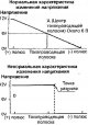
Rear window defroster
Defrosting of the rear window is carried out by a heater, which is a series of parallel conductors sprayed onto the glass. When electric current is passed through, the...
Defrosting of the rear window is carried out by a heater, which is a series of parallel conductors sprayed onto the glass. When electric current is passed through, the...

Supplemental Restraint System (SRS)
The Supplemental Restraint System (SRS) is designed to work in conjunction with the seat belts to help reduce injury to the driver and front passenger in a severe...
The Supplemental Restraint System (SRS) is designed to work in conjunction with the seat belts to help reduce injury to the driver and front passenger in a severe...

Driver's airbag and coil wire
Fig. 19.111. Driver's airbag and spiral wire: 1 - driver's airbag; 2 - steering wheel; 3 - spiral wire Removal Set the front wheels to straight ahead and remove the key...
Fig. 19.111. Driver's airbag and spiral wire: 1 - driver's airbag; 2 - steering wheel; 3 - spiral wire Removal Set the front wheels to straight ahead and remove the key...

Front passenger airbag
Fig. 19.119. Front passenger airbag (1) Removal Press the latches and lower the glove compartment down. Remove the screws, disconnect the connector and remove the...
Fig. 19.119. Front passenger airbag (1) Removal Press the latches and lower the glove compartment down. Remove the screws, disconnect the connector and remove the...
This section is available on: russian, bulgarian, belarusian, ukrainian, serbian, croatian, romanian, polish, slovak, hungarian
Similar materials for other Mitsubishi models
➤ Electrical equipment: Equipment and devices Mitsubishi Colt 2 and 3 (1983-1993)
➤ Electrical equipment: Equipment and devices Mitsubishi Lancer 9 (2000-2007, petrol)
➤ Electrical equipment: Equipment and devices Mitsubishi Galant 6 and 7 (1987-1998)
➤ Electrical equipment: Equipment and devices Mitsubishi L200 4 (2005-2014, diesel)
➤ General information: Salon equipment Mitsubishi Outlander 1 (2003-2008)
➤ Electrical equipment: Equipment and devices Mitsubishi Pajero 4 (2006-2021)
Link in different formats to this section
TEXTHTMLBB Code
- General information
- User manual
- Maintenance
- Power unit
- Petrol engines 4G9
- Diesel engines FBQT
- Diesel engines F9Q
- Cooling system
- Injection system (MPI)
- Injection system (GDI)
- Engine electrical equipment
- Transmission
- Clutch
- Mechanical gearbox
- Automatic gearbox
- Chassis and running gear
- Steering
- Brake system
- Front suspension and shafts
- Rear suspension
- Body and interior
- Exterior (external elements)
- Interior (internal elements)
- Doors, locks and windows
- Air conditioner
- Electrical equipment
- Equipment and devices
- Headlights and lighting
- Electrical circuits
- General information
- User manual
- Maintenance
- Power unit
- Petrol engines 4G9
- Petrol engines 4G1
- Diesel engines F9Q1
- Cooling system
- Fuel injection system GDI
- Fuel injection system MPI
- Diesel supply system F9Q1
- Ignition system
- Diesel preheating
- Transmission
- Clutch
- Mechanical gearbox
- Automatic gearbox
- Chassis and running gear
- Suspension and drive shafts
- Brake system
- Steering
- Body and interior
- Exterior (external elements)
- Interior (internal elements)
- Doors, locks and windows
- Heating and air conditioning
- Electrical equipment
- Power devices
- Equipment and devices