



Share with friends:
Heating and air conditioning system Mitsubishi Space Star

Heating, ventilation and air conditioning system
Technical data Heater type - full-flow with separate regulation of two flows Compressor - model MSC90 scroll type Dual pressure sensor, kPa high pressure switch ON ->...
Technical data Heater type - full-flow with separate regulation of two flows Compressor - model MSC90 scroll type Dual pressure sensor, kPa high pressure switch ON ->...

Checking the refrigerant level through the sight glass
The sight glass is an indicator of the refrigerant level in the air conditioning system. To check the level, clean the glass and start the engine (Fig. 18.1). Press the...
The sight glass is an indicator of the refrigerant level in the air conditioning system. To check the level, clean the glass and start the engine (Fig. 18.1). Press the...

Checking the compressor electromagnetic clutch
1. Disconnect the single-pin connector from the electromagnetic clutch (Fig. 18.2). Fig. 18.2. Location of the single-contact connector of the electromagnetic clutch 2....
1. Disconnect the single-pin connector from the electromagnetic clutch (Fig. 18.2). Fig. 18.2. Location of the single-contact connector of the electromagnetic clutch 2....
Air conditioning system refill
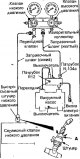
1. With the valve handles turned all the way out (valves closed), install the transition valve to the low pressure fitting of the measuring manifold (Fig. 18.3) Fig....
1. With the valve handles turned all the way out (valves closed), install the transition valve to the low pressure fitting of the measuring manifold (Fig. 18.3) Fig....

Topping up from a cylinder when the refrigerant level is low
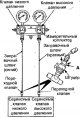
Fig. 18.5. Installing a transition valve when refilling from a cylinder with a low refrigerant level 1. Unscrew the filling valve handle as far as it will go (the valve...
Fig. 18.5. Installing a transition valve when refilling from a cylinder with a low refrigerant level 1. Unscrew the filling valve handle as far as it will go (the valve...
Air Conditioning Compressor Lubricant Oil
Air conditioning compressor lubricating oil circulates in the system when the compressor is running. When replacing any element of the air conditioning system with a...
Air conditioning compressor lubricating oil circulates in the system when the compressor is running. When replacing any element of the air conditioning system with a...
Performance check
1. The vehicle being tested must be installed in a location where there is no direct sunlight. 2. Close the high and low pressure valves of the measuring manifold. 3....
1. The vehicle being tested must be installed in a location where there is no direct sunlight. 2. Close the high and low pressure valves of the measuring manifold. 3....
Checking the fan relay
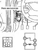
Remove the relay (Fig. 18.9). Fig. 18.9. Location of the fan relay and relay connector contacts Check the conductivity between the relay contacts. If the conductivity is...
Remove the relay (Fig. 18.9). Fig. 18.9. Location of the fan relay and relay connector contacts Check the conductivity between the relay contacts. If the conductivity is...

Replacing the cabin air filter
The filter traps dust particles and odors. 1. Remove the glove box. 2. Disconnect the wiring harness from the lower panel located on the front passenger side. 3. Remove...
The filter traps dust particles and odors. 1. Remove the glove box. 2. Disconnect the wiring harness from the lower panel located on the front passenger side. 3. Remove...

Air conditioning control unit
Removal Remove the lower center panel from the instrument panel. Remove the glove compartment. Remove the radio. Remove the screws, pull the heater, fan and air...
Removal Remove the lower center panel from the instrument panel. Remove the glove compartment. Remove the radio. Remove the screws, pull the heater, fan and air...

Heater and fan units
Removal Disconnect the cable from the negative battery terminal. Drain the coolant from the cooling system. Remove the heater, fan and air conditioning control unit....
Removal Disconnect the cable from the negative battery terminal. Drain the coolant from the cooling system. Remove the heater, fan and air conditioning control unit....
Heater Fan and Resistor
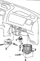
Fig. 18.17. Heater fan and resistor: 1 - resistor; 2 - heater fan; 3-motor for fresh/recirculated air supply flap drive Removal Disconnect the cable from the negative...
Fig. 18.17. Heater fan and resistor: 1 - resistor; 2 - heater fan; 3-motor for fresh/recirculated air supply flap drive Removal Disconnect the cable from the negative...

Evaporator — removal, disassembly, installation.
Note: In Figure 18.21 *1 bolts and nuts with flange are marked, and *2 - bolts and nuts with washers. Fig. 18.21. Evaporator: 1 - suction hose; 2 - tube B for...
Note: In Figure 18.21 *1 bolts and nuts with flange are marked, and *2 - bolts and nuts with washers. Fig. 18.21. Evaporator: 1 - suction hose; 2 - tube B for...

Air conditioning compressor
Removal Disconnect the cable from the negative battery terminal. Discharge the refrigerant from the air conditioning system. Remove the lower engine compartment splash...
Removal Disconnect the cable from the negative battery terminal. Discharge the refrigerant from the air conditioning system. Remove the lower engine compartment splash...

Air conditioning compressor electromagnetic clutch
Fig. 18.29. Compressor electromagnetic clutch: 1 - nut; 2 - rotor disk; 3 - gasket; 4 - retaining ring; 5 - rotor; 6 - retaining spring ring; 7 - electromagnetic clutch...
Fig. 18.29. Compressor electromagnetic clutch: 1 - nut; 2 - rotor disk; 3 - gasket; 4 - retaining ring; 5 - rotor; 6 - retaining spring ring; 7 - electromagnetic clutch...

Working with tubes, hoses and their connections
The location of the air conditioning system pipelines is shown in Figure 18.35. Fig. 18.35. Air conditioning system tubes and hoses: 1 - suction hose; 2 - tube B for...
The location of the air conditioning system pipelines is shown in Figure 18.35. Fig. 18.35. Air conditioning system tubes and hoses: 1 - suction hose; 2 - tube B for...

Condenser and condenser fan
Note: In Figure 18.36 *1 flange bolts are marked, and *2 - bolts with washer. Fig. 18.36. Condenser and condenser fan: 1 - condenser fan assembly with casing; 2 -...
Note: In Figure 18.36 *1 flange bolts are marked, and *2 - bolts with washer. Fig. 18.36. Condenser and condenser fan: 1 - condenser fan assembly with casing; 2 -...
This section is available on: russian, bulgarian, belarusian, ukrainian, serbian, croatian, romanian, polish, slovak, hungarian
Similar materials for other Mitsubishi models
➤ Power unit: Heater and air conditioner Mitsubishi Colt 2 and 3 (1983-1993)
➤ Body and interior: Heating system Mitsubishi Lancer 3 and 5 (1984-1992)
Link in different formats to this section
TEXTHTMLBB Code
- General information
- User manual
- Maintenance
- Power unit
- Petrol engines 4G9
- Diesel engines FBQT
- Diesel engines F9Q
- Cooling system
- Injection system (MPI)
- Injection system (GDI)
- Engine electrical equipment
- Transmission
- Clutch
- Mechanical gearbox
- Automatic gearbox
- Chassis and running gear
- Steering
- Brake system
- Front suspension and shafts
- Rear suspension
- Body and interior
- Exterior (external elements)
- Interior (internal elements)
- Doors, locks and windows
- Air conditioner
- Electrical equipment
- Equipment and devices
- Headlights and lighting
- Electrical circuits
- General information
- User manual
- Maintenance
- Power unit
- Petrol engines 4G9
- Petrol engines 4G1
- Diesel engines F9Q1
- Cooling system
- Fuel injection system GDI
- Fuel injection system MPI
- Diesel supply system F9Q1
- Ignition system
- Diesel preheating
- Transmission
- Clutch
- Mechanical gearbox
- Automatic gearbox
- Chassis and running gear
- Suspension and drive shafts
- Brake system
- Steering
- Body and interior
- Exterior (external elements)
- Interior (internal elements)
- Doors, locks and windows
- Heating and air conditioning
- Electrical equipment
- Power devices
- Equipment and devices