



Contents: Removal ⤓ Installation ⤓
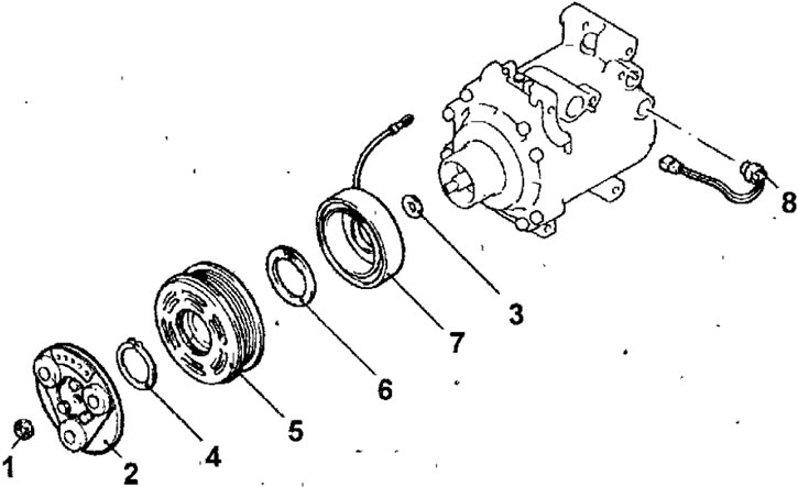
Fig. 18.29. Compressor electromagnetic clutch: 1 - nut; 2 - rotor disk; 3 - gasket; 4 - retaining ring; 5 - rotor; 6 - retaining spring ring; 7 - electromagnetic clutch coil; 8 - temperature sensor
Removal
- Using special tools MB991367 and MB991386, hold the rotor disk from turning, unscrew the nut and remove the rotor disk (Fig. 18.30).
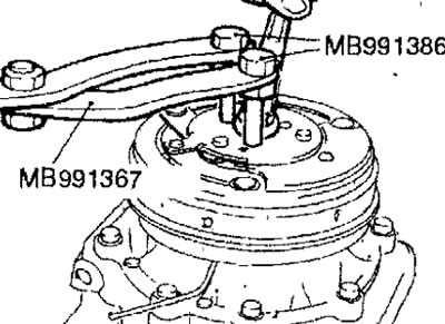
Fig. 18.30. Unscrewing the nut securing the electromagnetic clutch plate
- Remove the retaining ring, rotor and coil of the electromagnetic clutch and gasket.
Installation
- When installing the electromagnetic clutch coil, align the coil pin with the hole in the compressor housing (Fig. 18.31).
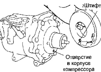
Fig. 18.31. Alignment of the electromagnetic clutch coil pin with the hole in the compressor housing
- Install the snap ring so that the conical surface faces the outside (Fig. 18.32).
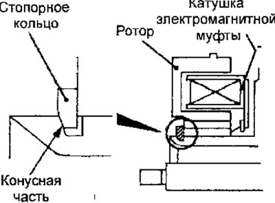
Fig. 18.32. Installation position of the spring retaining ring
- Align the mounting protrusion on the compressor shaft with the recess on the rotor disk and install the rotor disk on the shaft (Fig. 18.33).
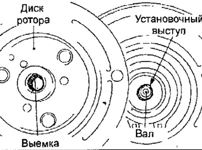
Fig. 18.33. Installing the plate on the compressor shaft
Using special tools MB991367 and MB991386, hold the rotor disk from turning and screw on the rotor disk fastening nut (Fig. 18.30).
- Use a feeler gauge to measure the air gap of the electromagnetic clutch (Fig. 18.34).
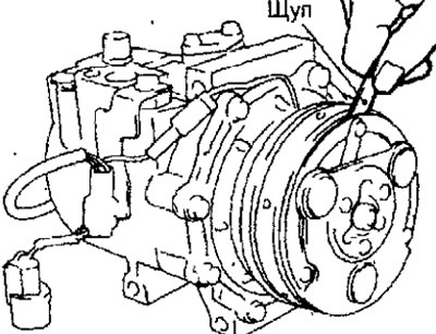
Fig. 18.34. Measuring the air gap of an electromagnetic clutch
Nominal clearance of the compressor electromagnetic clutch: 0.40-0.65 mm
[The article is based on data from the website: www.MitsubishiMan.ru]
Note: If the measured air gap of the compressor electromagnetic clutch does not correspond to the nominal value, adjust the gap by changing the number of adjusting shims