



Share with friends:
Vehicle Injection System (MPI) Mitsubishi Carisma


General information about the multipoint injection (MPI) system
Fig. 7.1. Location of SOHC injection system components: 1 – air conditioning compressor electromagnetic clutch relay; 2 – electromagnetic valve for purging the adsorber...
Fig. 7.1. Location of SOHC injection system components: 1 – air conditioning compressor electromagnetic clutch relay; 2 – electromagnetic valve for purging the adsorber...

Self-diagnosis function
If a malfunction occurs in one of the sensors or actuators related to the exhaust gas toxicity reduction systems, the engine malfunction indicator lamp lights up in the...
If a malfunction occurs in one of the sensors or actuators related to the exhaust gas toxicity reduction systems, the engine malfunction indicator lamp lights up in the...
Engine Malfunction Indicator Lamp
If a malfunction occurs in any of the following components of the multipoint injection (MPI) system, the engine malfunction indicator lamp in the instrument cluster...
If a malfunction occurs in any of the following components of the multipoint injection (MPI) system, the engine malfunction indicator lamp in the instrument cluster...

Cleaning the throttle body
1. Start the engine, warm it up until the coolant temperature is 80°C or higher, and then turn it off. 2. Disconnect the inlet hose from the throttle body. Fig. 7.3....
1. Start the engine, warm it up until the coolant temperature is 80°C or higher, and then turn it off. 2. Disconnect the inlet hose from the throttle body. Fig. 7.3....

Adjusting the throttle closed position switch and the position sensor (TPS) of vehicles without the TCL system
1. Connect the MUT-II device to the diagnostic connector. Fig. 7.4. Installing a 0.65 mm thick flat feeler gauge between the factory idle speed adjustment screw (Fixed...
1. Connect the MUT-II device to the diagnostic connector. Fig. 7.4. Installing a 0.65 mm thick flat feeler gauge between the factory idle speed adjustment screw (Fixed...

Adjusting the throttle valve closed position switch and accelerator pedal position sensor for vehicles with the TCL system
1. Connect the MUT-II device to the diagnostic connector. Fig. 7.5. Installing a 0.5 mm thick flat feeler gauge between the accelerator lever and the throttle lever: 1 –...
1. Connect the MUT-II device to the diagnostic connector. Fig. 7.5. Installing a 0.5 mm thick flat feeler gauge between the accelerator lever and the throttle lever: 1 –...

Adjusting the Throttle Lever Stop Screw (Fixed SAS)
Caution! Do not touch the Fixed SAS screw unless absolutely necessary, as its position has been adjusted with high precision at the factory. Attention! If such a need...
Caution! Do not touch the Fixed SAS screw unless absolutely necessary, as its position has been adjusted with high precision at the factory. Attention! If such a need...

Adjusting the engine's basic idle speed of the crankshaft
Caution! The nominal idle speed is adjusted at the factory using the idle speed adjustment screw (SAS) and usually does not require additional adjustment during...
Caution! The nominal idle speed is adjusted at the factory using the idle speed adjustment screw (SAS) and usually does not require additional adjustment during...

Relieving pressure in the fuel system
Since the fuel line is under high pressure, before removing the fuel rail, hose, etc., perform the following operations to reduce the fuel pressure and prevent fuel...
Since the fuel line is under high pressure, before removing the fuel rail, hose, etc., perform the following operations to reduce the fuel pressure and prevent fuel...

Checking the operation of the fuel pump
Check the operation of the fuel pump by forcibly turning it on using the MUT-II device. If the fuel pump does not work, then check it using the following method, and if...
Check the operation of the fuel pump by forcibly turning it on using the MUT-II device. If the fuel pump does not work, then check it using the following method, and if...

Checking the intake manifold air temperature sensor
Fig. 7.10. Air flow meter sensor connector contacts (1) (2) 1. Disconnect the connector from the air flow meter sensor (Fig. 7.10). 2. Measure the resistance between...
Fig. 7.10. Air flow meter sensor connector contacts (1) (2) 1. Disconnect the connector from the air flow meter sensor (Fig. 7.10). 2. Measure the resistance between...

Checking the coolant temperature sensor
Attention! When removing and installing the sensor, do not touch its connector (plastic part) with the tool. Fig. 7.12. Location of the coolant temperature sensor: A –...
Attention! When removing and installing the sensor, do not touch its connector (plastic part) with the tool. Fig. 7.12. Location of the coolant temperature sensor: A –...

Checking the Throttle Position Sensor (TPS)
1. Disconnect the throttle position sensor connector. Fig. 7.13. Location of connector contacts (1) and throttle position sensor (2) 2. Measure the resistance between...
1. Disconnect the throttle position sensor connector. Fig. 7.13. Location of connector contacts (1) and throttle position sensor (2) 2. Measure the resistance between...

Checking the fully closed throttle position switch for vehicles without the TCL system
Fig. 7.13. Location of connector contacts (1) and throttle position sensor (2) 1. Disconnect the throttle position sensor connector (see Fig. 7.13). 2. Check the circuit...
Fig. 7.13. Location of connector contacts (1) and throttle position sensor (2) 1. Disconnect the throttle position sensor connector (see Fig. 7.13). 2. Check the circuit...

Checking the oxygen sensor
1. Disconnect the oxygen sensor connector and connect the special tool (test wire harness) to the connector on the sensor side. Fig. 7.14. Checking the resistance of the...
1. Disconnect the oxygen sensor connector and connect the special tool (test wire harness) to the connector on the sensor side. Fig. 7.14. Checking the resistance of the...

Injectors — removal, inspection and installation
Checking the injector 1. Disconnect the connector from the injector. 2. Measure the resistance between the connector contacts. The nominal value is 13-16 Ohm at 20°C. 3....
Checking the injector 1. Disconnect the connector from the injector. 2. Measure the resistance between the connector contacts. The nominal value is 13-16 Ohm at 20°C. 3....
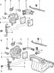
Throttle body — removal and installation
Removal Disconnect the cable from the negative battery terminal. To remove, follow these steps in sequence. 1. Drain the coolant from the engine cooling system. 2....
Removal Disconnect the cable from the negative battery terminal. To remove, follow these steps in sequence. 1. Drain the coolant from the engine cooling system. 2....

Disassembly and assembly of the throttle assembly
Cars without TCL system Disassembly To disassemble, perform the following operations in sequence. Fig. 7.22. Throttle body: 1 – bolt (2 Nm); 2 – throttle position...
Cars without TCL system Disassembly To disassemble, perform the following operations in sequence. Fig. 7.22. Throttle body: 1 – bolt (2 Nm); 2 – throttle position...

Fuel tank — removal and installation
Removal To remove, follow these steps in sequence. 1. Disconnect the cable from the negative terminal of the battery. 2. Drain the fuel from the fuel tank. 3. Relieve...
Removal To remove, follow these steps in sequence. 1. Disconnect the cable from the negative terminal of the battery. 2. Drain the fuel from the fuel tank. 3. Relieve...

Replacing the fuel filter
1. Remove residual pressure in the fuel line. 2. Remove the air inlet hose. Fig. 7.29. Location of the fuel filter 3. Holding the fuel filter with a wrench, unscrew the...
1. Remove residual pressure in the fuel line. 2. Remove the air inlet hose. Fig. 7.29. Location of the fuel filter 3. Holding the fuel filter with a wrench, unscrew the...
Replacing the fuel pump
1. Raise the rear seat cushion. 2. Remove the protective cover. 3. Relieve residual pressure in the fuel line to prevent fuel splashing in the event of a leak. 4....
1. Raise the rear seat cushion. 2. Remove the protective cover. 3. Relieve residual pressure in the fuel line to prevent fuel splashing in the event of a leak. 4....
This section is available on: russian, bulgarian, belarusian, ukrainian, serbian, croatian, romanian, polish, slovak, hungarian
Similar materials for other Mitsubishi models
➤ Power unit: Fuel injection MPI Mitsubishi Colt 4 and 5 (1991-2003)
➤ Power unit: MPI fuel injection system Mitsubishi Lancer 9 (2000-2007, petrol)
Link in different formats to this section
TEXTHTMLBB Code
- General information
- User manual
- Maintenance
- Power unit
- Petrol engines 4G9
- Diesel engines FBQT
- Diesel engines F9Q
- Cooling system
- Injection system (MPI)
- Injection system (GDI)
- Engine electrical equipment
- Transmission
- Clutch
- Mechanical gearbox
- Automatic gearbox
- Chassis and running gear
- Steering
- Brake system
- Front suspension and shafts
- Rear suspension
- Body and interior
- Exterior (external elements)
- Interior (internal elements)
- Doors, locks and windows
- Air conditioner
- Electrical equipment
- Equipment and devices
- Headlights and lighting
- Electrical circuits
- General information
- User manual
- Maintenance
- Power unit
- Petrol engines 4G9
- Petrol engines 4G1
- Diesel engines F9Q1
- Cooling system
- Fuel injection system GDI
- Fuel injection system MPI
- Diesel supply system F9Q1
- Ignition system
- Diesel preheating
- Transmission
- Clutch
- Mechanical gearbox
- Automatic gearbox
- Chassis and running gear
- Suspension and drive shafts
- Brake system
- Steering
- Body and interior
- Exterior (external elements)
- Interior (internal elements)
- Doors, locks and windows
- Heating and air conditioning
- Electrical equipment
- Power devices
- Equipment and devices