



Contents: Cars without TCL system ⤓ Accelerator Pedal Position Sensor…⤓ Throttle Position Sensor (TPS) ⤓ Cars with TCL system ⤓
Cars without TCL system
Disassembly
To disassemble, perform the following operations in sequence.
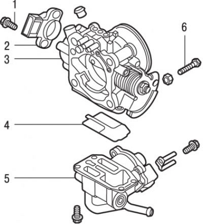
Fig. 7.22. Throttle body: 1 – bolt (2 Nm); 2 – throttle position sensor; 3 – throttle body; 4 – O-ring gasket; 5 – idle speed regulator housing assembly; 6 – factory idle speed adjustment screw (Fixed SAS, throttle stop screw)
1. Loosen the bolts and remove the throttle position sensor (Fig. 7.22).
2. Loosen the screws and remove the idle speed control housing assembly.
3. Remove the throttle body O-ring.
4. Remove the factory idle speed adjustment screw (Fixed SAS, throttle stop screw) from the throttle body.
Caution! The Fixed SAS screw is set correctly at the factory, so there is no need to unscrew it. If you still have to unscrew the factory idle speed adjustment screw (Fixed SAS), then after assembly, adjust the position of this screw.
Cleaning
Clean all throttle body parts.
Caution! Do not use solvent to clean the following parts:
- - throttle position sensor;
- - accelerator pedal position sensor;
- – idle speed regulator housing assembly.
Caution: Immersion of these parts in solvent will damage the insulation.
Wipe the parts with a clean cloth.
Make sure there are no deposits in the vacuum passage or fitting. Blow them out with compressed air.
Assembly
Installation is carried out in the reverse order of removal, taking into account the following.
Accelerator Pedal Position Sensor (APS)
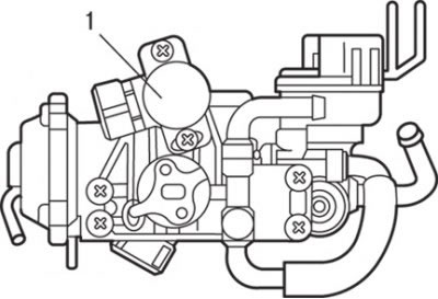
Fig. 7.23. Accelerator pedal position sensor (1)
1. Install the accelerator pedal position sensor (APS) as shown in Fig. 7.23 and tighten the screws that secure it.
2. Connect a multimeter between terminals "3" (APS sensor output signal) and "4" (APS sensor power supply) of the accelerator pedal position sensor connector and check that the resistance gradually increases when the throttle valve is slowly opened (until it is fully opened).
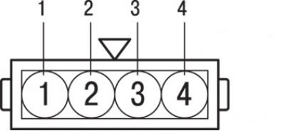
Fig. 7.24. Accelerator pedal position sensor connector: 1 - "mass"; 2 – sensor-switch for fully closed throttle position; 3 – power supply for the accelerator pedal position sensor; 4 – output signal of the accelerator pedal position sensor
3. Check the circuit between contact "2" (the fully closed throttle position switch) and contact "1" ("ground") (Fig. 7.24). When the throttle valve is fully closed, the circuit should be closed, and when the throttle valve is open, it should be open.
4. If the circuit is open with the throttle valve fully closed, turn the accelerator pedal position sensor housing clockwise and repeat the check.
5. If there is a malfunction in the sensor, replace the accelerator pedal position sensor.
Throttle Position Sensor (TPS)
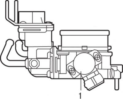
Fig. 7.25. Throttle position sensor (TPS) (1)
1. Install the throttle position sensor (TPS) as shown in Fig. 7.25 and tighten the screws that secure it.
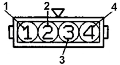
Fig. 7.26. Throttle position sensor connector: 1 – power supply for the throttle position sensor; 2 – output signal of the throttle position sensor; 3 – sensor-switch for fully closed throttle position; 4 – "mass"
2. Connect a multimeter between terminal "1" (Fig. 7.26) (power supply) and terminal "2" (output signal) of the throttle position sensor connector and check that the resistance gradually increases when the throttle valve is slowly opened (until it is fully opened).
3. For vehicles without the TCL system, check the circuit between terminal "3" (closed throttle position switch) and terminal "4" (ground) with the throttle valve fully closed and fully open.
4. If the circuit is open with the throttle valve fully closed, turn the throttle position sensor housing counterclockwise and repeat the test.
5. If there is a malfunction in the sensor, replace the throttle position sensor.
Cars with TCL system
Disassembly
To disassemble, perform the following operations in sequence.
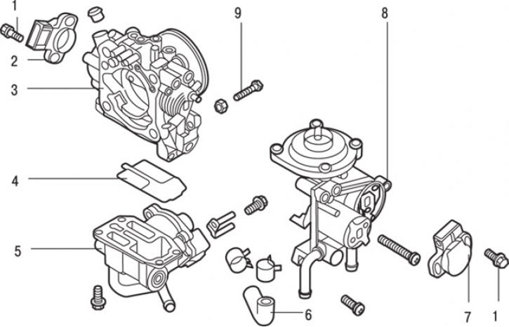
Fig. 7.27. Throttle body: 1 – bolt (2 Nm); 2 – Throttle Position Sensor (TPS); 3 – throttle body; 4 – O-ring gasket; 5 – idle speed regulator housing assembly; 6 – cooling system hose; 7 – Accelerator pedal position sensor (APS); 8 – lever assembly; 9 – factory idle speed adjustment screw (Fixed SAS, throttle stop screw)
1. Loosen the clamp and remove the cooling system hose 6 (Fig. 7.27).
2. Remove the bolts and throttle position sensor (TPS).
3. Loosen the bolts and remove the accelerator pedal position sensor (APS).
4. Loosen the bolts and remove the lever assembly.
5. Loosen the bolts and remove the idle speed control housing assembly and gasket 4.
6. Remove the factory idle speed adjustment screw (Fixed SAS, throttle stop screw).
Caution! The Fixed SAS screw is set correctly at the factory, so there is no need to unscrew it. If you still have to unscrew the factory idle speed adjustment screw (Fixed SAS), then after assembly, adjust the position of this screw.
Cleaning
Cleaning is carried out in the same way as for vehicles without the TCL system.
Assembly
Assembly is carried out in the same way as for vehicles without the TCL system.