



Share with friends:
Brake system of the car Mitsubishi Space Star

Brake system — technical data
Brake system of cars manufactured since 1999 Master brake cylinder type - dual-circuit internal diameter, mm — 23.81 Vacuum brake booster type - vacuum effective...
Brake system of cars manufactured since 1999 Master brake cylinder type - dual-circuit internal diameter, mm — 23.81 Vacuum brake booster type - vacuum effective...

Checking and adjusting the brake pedal position
Fig. 15.1. Location of brake system components without ABS Fig. 15.2. Elements of the parking brake system 1. Remove the floor carpet and measure the brake pedal...
Fig. 15.1. Location of brake system components without ABS Fig. 15.2. Elements of the parking brake system 1. Remove the floor carpet and measure the brake pedal...

Checking the brake light switch
Connect an ohmmeter to the contacts of the brake light switch connector and check the brake light switch circuit with the rod pressed and released (Fig. 15.8). If the...
Connect an ohmmeter to the contacts of the brake light switch connector and check the brake light switch circuit with the rod pressed and released (Fig. 15.8). If the...

Checking the brake booster
To perform a simple check of the brake booster, perform the following tests. 1. Start the engine and stop it after 1-2 minutes. Press the brake pedal several times with...
To perform a simple check of the brake booster, perform the following tests. 1. Start the engine and stop it after 1-2 minutes. Press the brake pedal several times with...

Checking the one-way vacuum valve
1. Remove the vacuum hose. Warning: Do not remove the one-way vacuum valve from the vacuum hose. 2. Check the operation of the one-way vacuum valve using a vacuum pump...
1. Remove the vacuum hose. Warning: Do not remove the one-way vacuum valve from the vacuum hose. 2. Check the operation of the one-way vacuum valve using a vacuum pump...

Checking the rear brake pressure regulator
1. Connect two pressure gauges to the inlet and outlet of the pressure regulator, respectively (Fig. 15.13). Fig. 15.13. Connecting pressure gauges to the input and...
1. Connect two pressure gauges to the inlet and outlet of the pressure regulator, respectively (Fig. 15.13). Fig. 15.13. Connecting pressure gauges to the input and...

Checking the brake fluid level sensor
1 Remove the cap from the brake system hydraulic fluid reservoir. 2. By pressing the brake fluid level sensor float, check the condition of the circuit between the...
1 Remove the cap from the brake system hydraulic fluid reservoir. 2. By pressing the brake fluid level sensor float, check the condition of the circuit between the...

Bleeding the hydraulic brake drive system
It is not recommended to use fluid drained from the brake system to fill the replenishment reservoir, as it is saturated with air and moisture and may be contaminated....
It is not recommended to use fluid drained from the brake system to fill the replenishment reservoir, as it is saturated with air and moisture and may be contaminated....

Checking and replacing front disc brake pads
Note: The brake pads are equipped with wear indicators which, when touching the brake disc, when the brake lining thickness reaches less than 2 mm, produce a squealing...
Note: The brake pads are equipped with wear indicators which, when touching the brake disc, when the brake lining thickness reaches less than 2 mm, produce a squealing...

Checking the brake disc
Warning: When servicing disc brakes, special attention must be paid to compliance with the technical requirements for disc brakes, which ensure the normal operation of...
Warning: When servicing disc brakes, special attention must be paid to compliance with the technical requirements for disc brakes, which ensure the normal operation of...

Checking the thickness of the brake shoe linings of drum brakes
1. Remove the brake drum. 2. In the area of greatest wear, measure the thickness of the brake shoe lining (Fig. 15.28). Fig. 15.28. Location for measuring the thickness...
1. Remove the brake drum. 2. In the area of greatest wear, measure the thickness of the brake shoe lining (Fig. 15.28). Fig. 15.28. Location for measuring the thickness...

Checking the inner diameter of the brake drum
1. Remove the brake drum. 2. Measure the inner diameter of the brake drum in several places (Fig. 15.29). Fig. 15.29. Measuring the inner diameter of the brake drum...
1. Remove the brake drum. 2. Measure the inner diameter of the brake drum in several places (Fig. 15.29). Fig. 15.29. Measuring the inner diameter of the brake drum...

Brake pedal
Removal Disconnect the cable from the negative terminal of the battery Remove the lower instrument panel trim. Remove the steering column assembly. Remove the brake...
Removal Disconnect the cable from the negative terminal of the battery Remove the lower instrument panel trim. Remove the steering column assembly. Remove the brake...

Master cylinder and brake booster
Warning: The hose marked *1 in figures 15.34 and 15.35 and the hose marked *in figure 15.36, after disconnecting from the reservoir, do not lower it below the master...
Warning: The hose marked *1 in figures 15.34 and 15.35 and the hose marked *in figure 15.36, after disconnecting from the reservoir, do not lower it below the master...

Front disc brake
Fig. 15.41. Front disc brake: 1 - brake hose; 2 - sealing gasket; 3 - support; 4 - brake disc Removal 1. Drain the brake fluid. 2. Remove the hollow bolt and disconnect...
Fig. 15.41. Front disc brake: 1 - brake hose; 2 - sealing gasket; 3 - support; 4 - brake disc Removal 1. Drain the brake fluid. 2. Remove the hollow bolt and disconnect...

Rear drum brakes
Removal 1. Loosen the parking brake adjusting nut. 2. Drain the brake fluid. 3. Remove the brake drum (Fig. 15.46). Fig. 15.46. Rear drum brake: 1 - brake drum; 2 -...
Removal 1. Loosen the parking brake adjusting nut. 2. Drain the brake fluid. 3. Remove the brake drum (Fig. 15.46). Fig. 15.46. Rear drum brake: 1 - brake drum; 2 -...

Working brake cylinder
Disassembly 1. Remove the protective cover (Fig. 15.51). Fig. 15.51. Working brake cylinder: 1 - dust cover: 2 - piston assembly; 3 - piston; 4 - piston cuff; 5 -...
Disassembly 1. Remove the protective cover (Fig. 15.51). Fig. 15.51. Working brake cylinder: 1 - dust cover: 2 - piston assembly; 3 - piston; 4 - piston cuff; 5 -...

Rear disc brakes
Removal 1. Drain the brake fluid. 2. Disconnect the parking brake cable (Fig. 15.53). Fig. 15.53. Rear disc brake: 1 - parking brake cable connection; 2 - brake hose; 3...
Removal 1. Drain the brake fluid. 2. Disconnect the parking brake cable (Fig. 15.53). Fig. 15.53. Rear disc brake: 1 - parking brake cable connection; 2 - brake hose; 3...

Repair of rear disc brake caliper
Disassembly 1. Unscrew the guide pin mounting bolts and remove the caliper from the caliper bracket (Fig. 15.58). Remove the brake pads. Fig. 15.58. Rear disc brake...
Disassembly 1. Unscrew the guide pin mounting bolts and remove the caliper from the caliper bracket (Fig. 15.58). Remove the brake pads. Fig. 15.58. Rear disc brake...

Checking the travel of the parking brake lever
1. Pull the parking brake lever with a force of approximately 196 N and count the number of clicks, which should be 5-7. Attention: It is necessary to strictly observe...
1. Pull the parking brake lever with a force of approximately 196 N and count the number of clicks, which should be 5-7. Attention: It is necessary to strictly observe...

Checking the Parking Brake Indicator Light Switch
Check the circuit between the switch terminal and the switch mounting bolt. When the lever is raised, the circuit should be closed, and when it is lowered, it should be...
Check the circuit between the switch terminal and the switch mounting bolt. When the lever is raised, the circuit should be closed, and when it is lowered, it should be...

Parking brake lever
Fig. 15.65. Parking cable lever: 1 - adjusting nut; 2 - nut holder; 3 - bracket; 4 — parking brake lever assembly; 5 - Parking brake indicator lamp switch; 6 - cable...
Fig. 15.65. Parking cable lever: 1 - adjusting nut; 2 - nut holder; 3 - bracket; 4 — parking brake lever assembly; 5 - Parking brake indicator lamp switch; 6 - cable...

Parking brake cable
Note: Do not bend or deform the parking brake cables, as this will cause them to operate harshly and fail prematurely. Removal Parking brake cable for vehicles with rear...
Note: Do not bend or deform the parking brake cables, as this will cause them to operate harshly and fail prematurely. Removal Parking brake cable for vehicles with rear...

Anti-lock braking system
The anti-lock braking system prevents the wheels from locking during sudden braking. Thanks to this, the car remains controllable during maximum braking. ABS is ready...
The anti-lock braking system prevents the wheels from locking during sudden braking. Thanks to this, the car remains controllable during maximum braking. ABS is ready...

Checking and clearing ABS fault codes
Using the MUT-II device Connect the MUT-II tool to the 16-pin diagnostic connector and check the diagnostic trouble codes (Fig. 15.70). Fig. 15.70. Connecting the MUT-II...
Using the MUT-II device Connect the MUT-II tool to the 16-pin diagnostic connector and check the diagnostic trouble codes (Fig. 15.70). Fig. 15.70. Connecting the MUT-II...
ABS Diagnostic Trouble Codes
Code Malfunction 11 Open circuit of the right front wheel speed sensor 12 Open circuit of the left front wheel speed sensor 13 Open circuit of the right rear wheel speed...
Code Malfunction 11 Open circuit of the right front wheel speed sensor 12 Open circuit of the left front wheel speed sensor 13 Open circuit of the right rear wheel speed...
Checking the ABS Warning Light
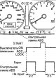
Check the ABS warning lamp as follows (Fig. 15.73). Fig. 15.73. Location of the ABS indicator lamp and its operating cycles 1. After turning the key in the ignition...
Check the ABS warning lamp as follows (Fig. 15.73). Fig. 15.73. Location of the ABS indicator lamp and its operating cycles 1. After turning the key in the ignition...

Checking the output voltage of the wheel speed sensor
1. Raise the vehicle and release the parking brake lever. 2. Pull the lock in the direction of the arrow shown in Figure 15.74 and disconnect the connector from the...
1. Raise the vehicle and release the parking brake lever. 2. Pull the lock in the direction of the arrow shown in Figure 15.74 and disconnect the connector from the...

Starting the engine with a completely discharged battery
If, with a completely discharged battery, an external power source is connected via jumper wires to start the engine and the car immediately starts moving (without...
If, with a completely discharged battery, an external power source is connected via jumper wires to start the engine and the car immediately starts moving (without...
Hydraulic block
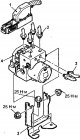
Removal 1. Drain the brake fluid. 2. Remove the air conditioner relay box. 3. Pull the lock in the direction of the arrow shown in figure 15.74 , and disconnect the...
Removal 1. Drain the brake fluid. 2. Remove the air conditioner relay box. 3. Pull the lock in the direction of the arrow shown in figure 15.74 , and disconnect the...

Wheel speed sensor
Removal 1. Check the output voltage of the wheel speed sensor. Front sensor 1. Loosen the bolts and remove the front wheel speed sensor (Fig. 15.79). Fig. 15.79. Front...
Removal 1. Check the output voltage of the wheel speed sensor. Front sensor 1. Loosen the bolts and remove the front wheel speed sensor (Fig. 15.79). Fig. 15.79. Front...
This section is available on: russian, bulgarian, belarusian, ukrainian, serbian, croatian, romanian, polish, slovak, hungarian
Similar materials for other Mitsubishi models
➤ Chassis and running gear: Brake system Mitsubishi Colt 4 and 5 (1991-2003)
➤ Chassis and running gear: Brake system Mitsubishi Lancer 3 and 5 (1984-1992)
➤ Chassis and running gear: Brake system Mitsubishi Galant 5 (1983-1989, petrol)
➤ Chassis and running gear: Brake system Mitsubishi L200 4 (2005-2014, diesel)
➤ Chassis and running gear: Brake system Mitsubishi Outlander 1 (2003-2008)
➤ Chassis and running gear: Brake system Mitsubishi Pajero 4 (2006-2021)
Link in different formats to this section
TEXTHTMLBB Code
- General information
- User manual
- Maintenance
- Power unit
- Petrol engines 4G9
- Diesel engines FBQT
- Diesel engines F9Q
- Cooling system
- Injection system (MPI)
- Injection system (GDI)
- Engine electrical equipment
- Transmission
- Clutch
- Mechanical gearbox
- Automatic gearbox
- Chassis and running gear
- Steering
- Brake system
- Front suspension and shafts
- Rear suspension
- Body and interior
- Exterior (external elements)
- Interior (internal elements)
- Doors, locks and windows
- Air conditioner
- Electrical equipment
- Equipment and devices
- Headlights and lighting
- Electrical circuits
- General information
- User manual
- Maintenance
- Power unit
- Petrol engines 4G9
- Petrol engines 4G1
- Diesel engines F9Q1
- Cooling system
- Fuel injection system GDI
- Fuel injection system MPI
- Diesel supply system F9Q1
- Ignition system
- Diesel preheating
- Transmission
- Clutch
- Mechanical gearbox
- Automatic gearbox
- Chassis and running gear
- Suspension and drive shafts
- Brake system
- Steering
- Body and interior
- Exterior (external elements)
- Interior (internal elements)
- Doors, locks and windows
- Heating and air conditioning
- Electrical equipment
- Power devices
- Equipment and devices