



Contents: Removal ⤓ Installation ⤓
Removal
1. Loosen the parking brake adjusting nut.
2. Drain the brake fluid.
3. Remove the brake drum (Fig. 15.46).
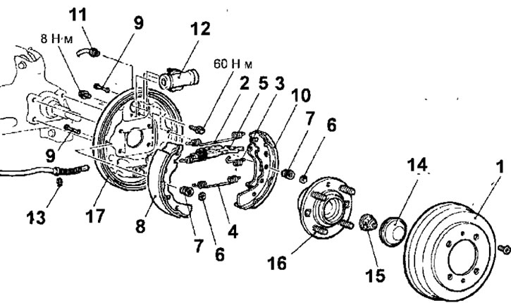
Fig. 15.46. Rear drum brake: 1 - brake drum; 2 - upper return spring; 3 - automatic regulator spring; 4 - lower return spring; 5 - automatic clearance adjuster assembly; 6 - brake shoe holder cap; 7 - brake shoe holder spring; 8 - brake shoe; 9 - Brake shoe holder; 10 - brake shoe and parking brake lever assembly; 11 - brake pipe connection, 15 Nm; 12-working brake cylinder; 13 - retaining ring; 14 - hub cap; 15 - hub flange nut, 180 Nm; 16 - rear wheel hub assembly; 17 - drum brake support shield
4. Remove the upper brake shoe return spring.
5. Remove the automatic regulator spring.
6. Remove the automatic regulator lever.
7. Remove the automatic regulator assembly.
8. Remove the lower brake shoe return spring.
9. Remove the brake shoe holder cap.
10. Remove the brake shoe retainer spring.
11. Remove the brake shoe and lining assembly. Do not press the brake pedal until the brake shoes are installed. To prevent the pistons from falling out of the working brake cylinder, secure the pistons with a suitable rubber band or wire.
12. Remove the brake shoe and parking brake lever assembly.
13. Move the parking brake actuator lever from the removed brake shoe to the new brake shoe. Use a flat-head screwdriver to release the retainer and remove it from the removed brake shoe (Fig. 15.47).
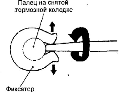
Fig. 15.47. Using a screwdriver to remove the retainer
14. Remove the convex washer.
15. Remove the parking brake lever.
16. Unscrew the nut and disconnect the brake pipe from the working brake cylinder. Unscrew the bolts and remove the working brake cylinder.
17. Remove the retaining ring.
18. Remove the hub cap.
19. Unscrew the hub flange nut.
20. Remove the rear wheel hub assembly.
21. Remove the drum brake support shield.
Installation
1. Installation is carried out in the reverse order of removal, taking into account the following.
2. Install the parking brake actuator lever onto the brake shoe, while installing the spherical washer in the position shown in Figure 15.48.
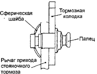
Fig. 15.48. Spherical washer installation position
3. Install the retainer and squeeze it with pliers (Fig. 15.49).
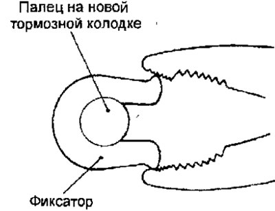
Fig. 15.49. Installing the parking brake lever mounting clamp
4. Clean the rear brake components. Apply high-temperature lubricant SAE J310, NLGI No.1 (Fig. 15.50) to the contact points of the shoes with the drum brake backing plate, brake cylinder and brake shoe support. Avoid getting lubricant on the friction linings of the brake shoes.
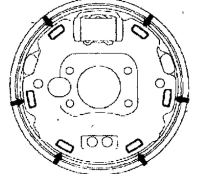
Fig. 15.50. Application locations of high-temperature lubricant SAE J310, NLGI No.1
5. Remove air from the hydraulic drive of the brake system.
6. Adjust the travel of the parking brake lever.