



Share with friends:
Car air conditioner Mitsubishi Carisma


General information about the air conditioning system
Attention! Applies to servicing of vehicles equipped with an additional passive safety system (SRS). Unqualified maintenance or repair of any component of the SRS system...
Attention! Applies to servicing of vehicles equipped with an additional passive safety system (SRS). Unqualified maintenance or repair of any component of the SRS system...
Safety precautions when working with the air conditioning system
Refrigerant R-134a is a fluorinated hydrocarbon CFH, in which chlorine atoms are replaced by hydrogen atoms, so it does not have a harmful effect on the ozone layer of...
Refrigerant R-134a is a fluorinated hydrocarbon CFH, in which chlorine atoms are replaced by hydrogen atoms, so it does not have a harmful effect on the ozone layer of...
Troubleshooting issues
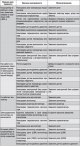
The main faults of the air conditioning system, probable causes and methods of elimination are given in Table 18.1. Table 18.1. Main faults of the air conditioning...
The main faults of the air conditioning system, probable causes and methods of elimination are given in Table 18.1. Table 18.1. Main faults of the air conditioning...
Noises generated by the air conditioning compressor
First, it is necessary to determine the causes of the noise. These include: weather conditions, vehicle speed, which gear is engaged or in neutral, engine temperature,...
First, it is necessary to determine the causes of the noise. These include: weather conditions, vehicle speed, which gear is engaged or in neutral, engine temperature,...

Checking the refrigerant level through the sight glass
Fig. 18.1. Location of the inspection window (1) for checking the refrigerant level The sight glass is an indicator of the refrigerant level in the air conditioning...
Fig. 18.1. Location of the inspection window (1) for checking the refrigerant level The sight glass is an indicator of the refrigerant level in the air conditioning...
Checking the electromagnetic clutch of the air conditioner compressor
1. Disconnect the connector (1P) from the electromagnetic clutch. 2. Using an additional wire, connect the positive terminal of the battery to the terminal of the clutch...
1. Disconnect the connector (1P) from the electromagnetic clutch. 2. Using an additional wire, connect the positive terminal of the battery to the terminal of the clutch...
Checking the receiver/dryer
1. Turn on the air conditioner and check the temperatures of the tubes at the inlet and outlet of the receiver/dryer. 2. If a temperature difference is felt, the...
1. Turn on the air conditioner and check the temperatures of the tubes at the inlet and outlet of the receiver/dryer. 2. If a temperature difference is felt, the...

Working with tubes, hoses and their connections
Fig. 18.2. Air conditioning system pipelines: 1 – flange bolt (25 Nm) or bolt with washer (30 Nm); 2 – receiver bracket; 3 – flange bolt (10 Nm) or bolt with washer (6...
Fig. 18.2. Air conditioning system pipelines: 1 – flange bolt (25 Nm) or bolt with washer (30 Nm); 2 – receiver bracket; 3 – flange bolt (10 Nm) or bolt with washer (6...

Heater control panel and manual air conditioner switch
Removal To remove the heater control panel assembly and air conditioner switch, perform the following steps. 1. Disconnect the cable from the negative terminal of the...
Removal To remove the heater control panel assembly and air conditioner switch, perform the following steps. 1. Disconnect the cable from the negative terminal of the...

Panel and electronic control unit of air conditioning with automatic control
Removal To remove the air conditioner control panel and electronic control unit, perform the following operations. 1. Disconnect the cable from the negative terminal of...
Removal To remove the air conditioner control panel and electronic control unit, perform the following operations. 1. Disconnect the cable from the negative terminal of...

Electric motors for air conditioner damper control drives with automatic control
Removal To remove the air damper control drive motors, perform the following operations. 1. Disconnect the cable from the negative terminal of the battery. 2. Remove the...
Removal To remove the air damper control drive motors, perform the following operations. 1. Disconnect the cable from the negative terminal of the battery. 2. Remove the...

Heater and heater radiator — removal and installation
Removal To remove the heater and heater radiator, perform the following operations. 1. Disconnect the cable from the negative terminal of the battery. 2. Drain the...
Removal To remove the heater and heater radiator, perform the following operations. 1. Disconnect the cable from the negative terminal of the battery. 2. Drain the...

Heater Fan and Resistor — Removal and Installation
Removal To remove, follow these steps. 1. Disconnect the cable from the negative terminal of the battery. Caution: When removing and installing the floor console on...
Removal To remove, follow these steps. 1. Disconnect the cable from the negative terminal of the battery. Caution: When removing and installing the floor console on...

Ventilation system air ducts — removal and installation
Removal 1. Disconnect the cable from the negative terminal of the battery. Fig. 18.16. Air ducts of the ventilation system: 1 – windshield deflector; 2 – side window...
Removal 1. Disconnect the cable from the negative terminal of the battery. Fig. 18.16. Air ducts of the ventilation system: 1 – windshield deflector; 2 – side window...

Air Purification Filter — Checking and Replacing
Removal To remove the air cleaning filter, follow these steps. 1. Disconnect the cable from the negative terminal of the battery. Caution! After the power is turned off...
Removal To remove the air cleaning filter, follow these steps. 1. Disconnect the cable from the negative terminal of the battery. Caution! After the power is turned off...
Cleaning the collector and ionizer
1. Mix a weak alkali or alkaline solvent with warm (no more than 60°C) water in a container and, after immersing the collector and ionizer in the solution, leave them in...
1. Mix a weak alkali or alkaline solvent with warm (no more than 60°C) water in a container and, after immersing the collector and ionizer in the solution, leave them in...

Photocell — Removal, Checking and Installation
Examination If the air flow rate from the fan decreases (cover the area where the photocell is located with your hand), this means that the photocell is working...
Examination If the air flow rate from the fan decreases (cover the area where the photocell is located with your hand), this means that the photocell is working...
Heater coolant temperature sensor
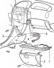
Removal To remove, follow these steps. 1. Disconnect the cable from the negative terminal of the battery. Fig. 18.22. Heater coolant temperature sensor: 1 – bottom...
Removal To remove, follow these steps. 1. Disconnect the cable from the negative terminal of the battery. Fig. 18.22. Heater coolant temperature sensor: 1 – bottom...

Topping up the air conditioning system from a cylinder when the refrigerant level is low
Fig. 18.26. Refilling the air conditioning system from a cylinder: 1 – valve open; 2 – valve closed; 3 – container with refrigerant; 4 – charging valve; 5 – transition...
Fig. 18.26. Refilling the air conditioning system from a cylinder: 1 – valve open; 2 – valve closed; 3 – container with refrigerant; 4 – charging valve; 5 – transition...
This section is available on: russian, bulgarian, belarusian, ukrainian, serbian, croatian, romanian, polish, slovak, hungarian
Similar materials for other Mitsubishi models
➤ Electrical equipment: Air conditioner Mitsubishi Pajero 4 (2006-2021)
Link in different formats to this section
TEXTHTMLBB Code
- General information
- User manual
- Maintenance
- Power unit
- Petrol engines 4G9
- Diesel engines FBQT
- Diesel engines F9Q
- Cooling system
- Injection system (MPI)
- Injection system (GDI)
- Engine electrical equipment
- Transmission
- Clutch
- Mechanical gearbox
- Automatic gearbox
- Chassis and running gear
- Steering
- Brake system
- Front suspension and shafts
- Rear suspension
- Body and interior
- Exterior (external elements)
- Interior (internal elements)
- Doors, locks and windows
- Air conditioner
- Electrical equipment
- Equipment and devices
- Headlights and lighting
- Electrical circuits
- General information
- User manual
- Maintenance
- Power unit
- Petrol engines 4G9
- Petrol engines 4G1
- Diesel engines F9Q1
- Cooling system
- Fuel injection system GDI
- Fuel injection system MPI
- Diesel supply system F9Q1
- Ignition system
- Diesel preheating
- Transmission
- Clutch
- Mechanical gearbox
- Automatic gearbox
- Chassis and running gear
- Suspension and drive shafts
- Brake system
- Steering
- Body and interior
- Exterior (external elements)
- Interior (internal elements)
- Doors, locks and windows
- Heating and air conditioning
- Electrical equipment
- Power devices
- Equipment and devices