



Contents: Removal ⤓ Installation ⤓
Removal
To remove, follow these steps.
1. Disconnect the cable from the negative terminal of the battery.
Caution: When removing and installing the floor console on vehicles with the SRS system, do not allow the console to hit the SRS control unit or other system components.

Fig. 18.13. Electric heater fan and resistor: A - cars not equipped with air conditioning; B – vehicles equipped with air conditioning; 1 – bottom cover; 2 – resistor; 3 – clamp; 4 – connecting air duct (cars without air conditioning); 5 – flange nut (25 Nm) or nut and washer (11 Nm); 6 – heater fan and electric motor; 7 – heater fan unit; 8 – instrument panel; 9 – flange bolt (25 Nm) or bolt and washer (11 Nm); 10 – evaporator (cars equipped with air conditioning); 11 – electronic control unit of the automatic compressor (cars equipped with air conditioning)
2. Remove the bottom cover 1 (Fig. 18.13).
3. Loosen the screws and remove resistor 2.
4. Loosen the screws, disconnect the electrical connector and remove the electronic control unit 11 of the automatic compressor (vehicles equipped with air conditioning).
5. Remove the instrument panel.
6. Remove the clamps 3. To do this, use a Phillips-head screwdriver to push the pin inward (in the center of the clamp) to a depth of about 2 mm, then pull the clamp outward.
Caution: Do not push the pin deeper than necessary, this may damage the spacer or the pin may fall inside.
7. Remove the connecting air duct 4 (cars without air conditioning).
8. Remove the evaporator 10 (vehicles equipped with air conditioning).
9. Loosen the screws, disconnect the electrical connector and remove fan 6 with the heater electric motor.
Installation
Installation is carried out in the reverse order of removal, taking into account the following.
1. Before installation, check the serviceability of the electric motor and heater resistor.
2. When applying battery voltage to the terminals of the electric motor, make sure that the motor shaft rotates. Also make sure that there are no extraneous noises or sounds.
3. Using a tester, measure the resistance between the terminals of the heater resistor connector.
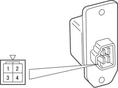
Fig. 18.14. Location of contacts on the resistor connector
Resistance between the contacts of the resistor connector (Fig. 18.14), Ohm:
- 3–2 (LO) — 2,30;
- 3–4 (ML) — 1,10;
- 3–1 (MN) — 0.40.
4. Install the pin, then insert the clamp into the hole.
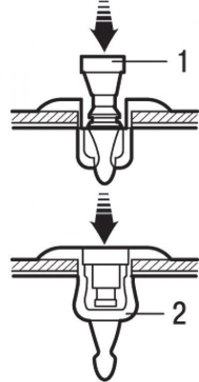
Fig. 18.15. Installing the clamp: 1 – pin; 2 – spacer
5. Push the pin in until its head is flush with the spacer (Fig. 18.15).