



Contents: Checking the refrigerant level…⤓ Checking the electromagnetic clutch ⤓ Checking the dual pressure sensor ⤓ Refueling ⤓
Checking the refrigerant level through the sight glass
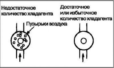
Start the engine.
Turn on the air conditioner and set it to maximum cooling mode.
Maintain engine speed at 1500 min⁻¹.
Determine the refrigerant level through the sight glass.
Caution: Use pressure reducing valve.
Attention! Please contact the refrigerant charging station because the user cannot correctly assess the amount of refrigerant in the system through the sight glass.
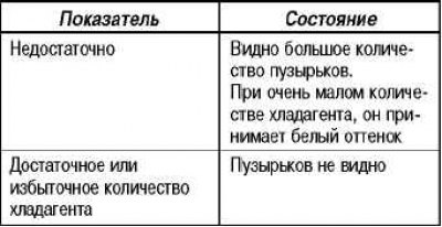
Checking the electromagnetic clutch
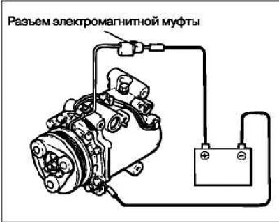
Disconnect the electromagnetic clutch connector from the clutch itself.
Connect the (+) battery terminal to the electromagnetic clutch connector.
If the electromagnetic clutch is in good working order, a "click" should be heard. If there is no contact ("click") between the drive pulley and the rotor, this indicates a malfunction.
Checking the dual pressure sensor
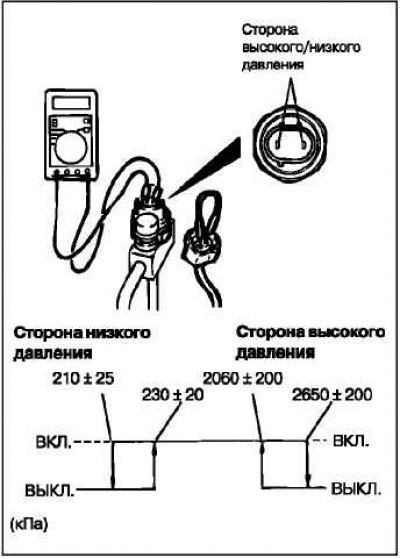
Disconnect the dual pressure sensor connector and connect the high/low pressure side terminals located on the wire harness side as shown in the illustration.
Connect the gauge manifold to the service valve on the high pressure side of the refrigerant line.
When the high/low pressure side of the dual pressure sensor is under the operating pressure, the measured resistance should not exceed 2 ohms. If the circuit is open, replace the sensor.
Refueling
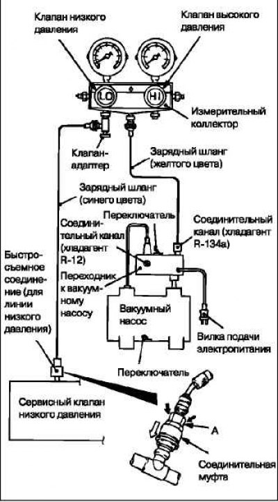
With the handles turned all the way back (valve closed), install the adapter valve on the low pressure side of the measuring manifold.
Connect the charging hose (blue) to the adapter valve.
Connect the quick release coupling (for low pressure) to the charging hose (blue).
Caution! Use only those devices and tools that are compatible with R134a refrigerant.
Caution: To install a quick-release coupling, press down on the coupling section and also run your hand along the hose to be connected to ensure there are no kinks.
Connect the quick release coupling (for low pressure) to the low pressure service valve.
Caution! The low pressure service valve must be connected to the flexible supply hose.
Close the high and low pressure valves on the measuring manifold.
Caution: Be sure to connect the vacuum pump power connector to the vacuum pump adapter, and then connect the adapter with the power connector to a 100V source.
Install the vacuum pump adapter to the vacuum pump.
Connect the charging hose (yellow) to the R-134a refrigerant connection port of the vacuum pump adapter.
Tighten the adapter valve handle (valve open).
Open the low pressure valve of the measuring manifold.
Set the vacuum pump switch to the ON position.
Caution: Even if the vacuum pump switch is set to the ON position, the vacuum pump will not operate due to the connection made in step 6.
Caution! Do not use the air conditioner compressor to remove refrigerant.

Turn the vacuum pump adapter switch to the R134a side to start the vacuum pump.
The refrigerant is removed at a vacuum of no more than 100 kPa (takes about 10 minutes).
Warning! Do not turn on the air conditioner compressor under vacuum: this will damage it.
Loosen the adapter valve completely (valve closed), turn off the vacuum pump with the switch. Then leave everything for five minutes.
Check the system for leaks (the vacuum value should not decrease).
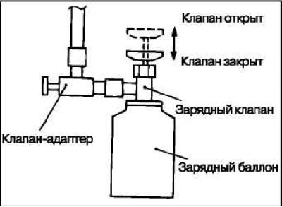
Connect the valve to the charging cylinder (with refrigerant) with the valve handle fully released (valve closed).
Completely unscrew the valve-adapter tap (valve closed), remove it from the measuring manifold and install the charging cylinder in its place.
Tighten the charging valve handle (valve closed) to pierce the charging cylinder.
Caution! If the charging cylinder is turned upside down, liquid refrigerant may flow into the compressor and damage it with liquid pressure. Keep the charging cylinder upright (not upside down) to ensure that the refrigerant charges the system in a gaseous state.
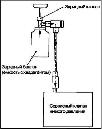
Turn the charging valve handle back (valve open) and tighten the adapter valve handle (valve open) to charge the system with refrigerant.
If the refrigerant does not fill the system, turn the adapter valve back until it stops (valve closed).
Check for gas leaks using a leak detector. If there are leaks, tighten the connections and repeat the refrigerant filling procedure from step (11).
Caution: A leak detector for R-134a refrigerant must be used.
Start the engine.
Turn on the air conditioner, set the minimum temperature mode (MAX. COOL).
Maintain engine speed at 1,500 rpm.
Caution! If the charging cylinder is turned upside down, liquid refrigerant may flow into the compressor and damage it with liquid pressure. Keep the charging cylinder upright (not upside down) to ensure that the refrigerant charges the system in a gaseous state.
Tighten the adapter valve handle (valve open) to fill the system with the required amount of refrigerant.
After filling the system with refrigerant, turn the adapter valve back until it stops (valve closed).
Tighten the charging valve handle (valve closed). Disconnect the quick-release connector (for low pressure) from the low pressure service valve.
Disconnect the charging cylinder.
Caution: If the charging cylinder still contains some refrigerant, close the charging valve and adapter valve tightly, which will save refrigerant for the next charging.