



Contents: Checking for damage to high-voltage…⤓ Checking the electrolyte level in…⤓ Visual inspection of SRS system…⤓ Front impact sensors ⤓ Side impact sensors ⤓ Electronic control unit of the SRS…⤓ Airbag module, steering wheel and…⤓ Alignment of installation marks ⤓ Front seat assembly with side airbag ⤓ Seat belts with pretensioners ⤓ Instrument cluster wiring harness/…⤓ Checking after installation of SRS…⤓
Checking for damage to high-voltage wires
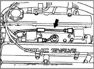
Check the high-voltage wires and spark plug tips for damage, weakening of the contact pressure, and also check that they are installed correctly.
Check for contamination on the contacts of high-voltage wires, spark plugs and ignition coils, etc.
If there is contamination, clean it; if the elements are damaged, replace them.
Checking the electrolyte level in the battery
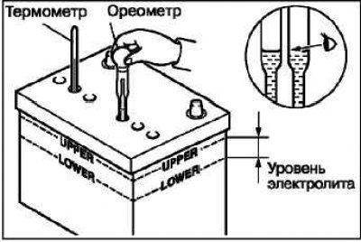
Check if the electrolyte level is between the upper and lower level marks.
Warning! If the electrolyte level is below the low level mark, the battery may explode during operation.
Caution: If the electrolyte level is above the upper level mark, electrolyte leakage may occur.
Use a thermometer and a hydrometer to check the specific gravity of the electrolyte.
Standard value: 1.220–1.290 (at 20°C).
The density of the electrolyte changes with temperature, so to bring the density values to a certain temperature, use the formula below. To determine the permissibility of a given electrolyte density, use the calculated value.
D20 = (t – 20) x 0.0007 + Dt D20: electrolyte density reduced to a temperature of 20°C. Dt – oreometer readings, t – thermometer readings.
Visual inspection of SRS system components
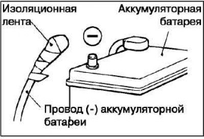
Turn the ignition key to the "LOCK" position, disconnect the negative battery cable and insulate it.
Caution: Wait at least 60 seconds after disconnecting the battery before proceeding with further work.
Front impact sensors
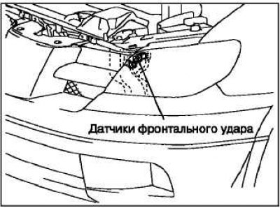
Check for rust on the headlight mounting panel.
Check that there are no signs of rust or mechanical damage on the front impact sensor housing.
Check the condition of the sensor wiring harness, the presence of pinching. Check for damage and deformation on the connectors and terminals.
Side impact sensors
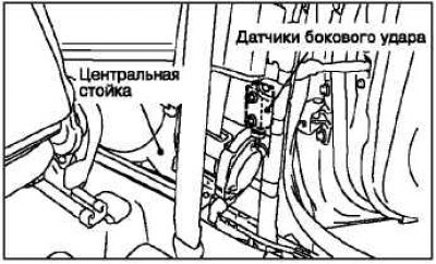
Check for rust and deformation on the center pillar
Check that there are no signs of rust or mechanical damage on the side impact sensor housing.
Check the condition of the sensor wiring harness, the presence of pinching. Check for damage and deformation on the connectors and terminals.
Electronic control unit of the SRS system
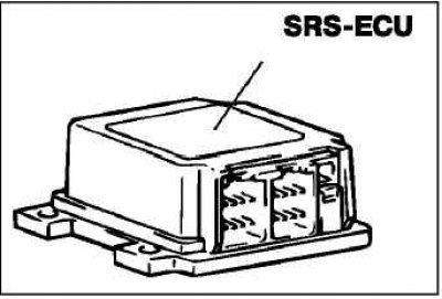
Check for dents, rust, and cracks on the brackets and SRS-ECU housing.
Warning! If the SRS-ECU is not installed correctly, the supplemental restraint system may not operate, which could result in serious injury or death to the driver and front passenger.
Check for damage and corrosion on the connectors. Replace the SRS-ECU if defects are found during inspection.
Airbag module, steering wheel and clock spring
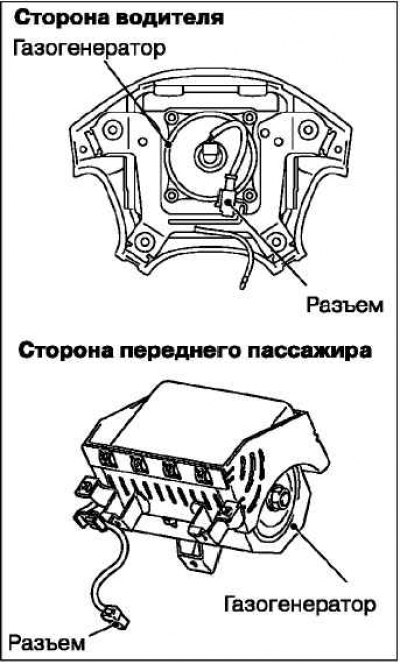
Remove the airbag modules, steering wheel and clock spring.
Caution: The removed airbag module must be stored in a clean, dry place, with the front side facing up.
Check for dents, cracks, deformations on the front surface (casing) of the module.
Check for damage to connectors, deformation of contacts and kinks in the wiring harness.
Check the gas generator for dents, cracks, and deformations.
Check for damage to connectors and wire harnesses, and deformation of contacts.
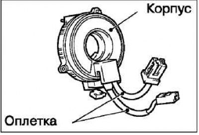
Check for damage to the connectors and braiding, deformation of the clock spring contacts.
Visually inspect the clock spring housing for damage.
Attention! If damage is detected, these parts must be replaced.
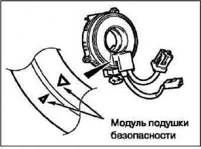
Check for excessive play in the steering wheel.
Align the timing marks on the clock spring and install it with the steering wheel turned to the straight-ahead position.
Alignment of installation marks
Turn the clock spring fully clockwise, then back it out 3/4 turn and align the timing marks.
Warning! If the timing marks on the clock spring are not aligned accurately, the steering wheel will not turn fully when turned, or the flat wire inside the clock spring may be damaged, causing the SRS to malfunction and possibly causing serious injury to the driver or front passenger.
Install the steering column covers, steering wheel and air bag module.
Check for noise or binding when turning the steering wheel.
Warning! If any of these components are not installed correctly, the SRS system may not operate, which could result in serious injury or death to the driver and front passenger.
Front seat assembly with side airbag
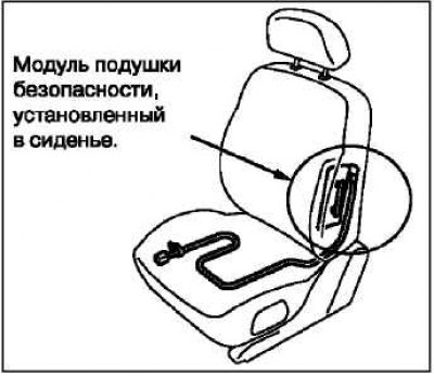
Check for dents or deformation on the side airbag module.
Check for damage to connectors, deformation of contacts and kinks in wire harnesses.
Seat belts with pretensioners
Check the seat belt pretensioner for dents or deformation.
Check that the pretensioner is installed correctly on the vehicle body.
Instrument cluster wiring harness/ Front vehicle wiring harness/ Floor wiring harness
Warning! The SRS system will not activate if the SRS wiring harnesses or connectors are damaged or improperly connected; this, in turn, can lead to serious injuries to the driver and passengers.
Checking after installation of SRS system components
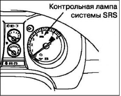
Reconnect the negative battery cable. Turn the ignition switch to the ON position. Does the SRS indicator light come on for about 7 seconds, go out, and then come on again for at least 5 seconds? If so, the SRS is normal.