



This section describes the maintenance and repair procedures for some elements of the on-board electrical equipment system. In addition, diagnostic procedures for general electrical equipment faults are considered.
The vehicle is equipped with a Controller Area Network (CAN) multiplexed communication device. It combines individual control devices into a common circuit (data bus), which provides the following advantages: fast data transfer from one device to another, space savings due to the use of small boards and components, and a reduction in the number of sensors due to their multifunctionality.
The principle of operation of CAN: instead of a separate conductor for each signal, only two common wires are used, which allows you to simultaneously receive information about the state of most devices and sensors without using separate toggle switches.
The CAN bus, receiving important information (for example, about a malfunction), records it in its memory.
Attention! When replacing fuses, do not use screwdrivers or metal tools, as this may cause a short circuit in the electrical circuits.
Warning! It is prohibited to disconnect the ignition switch and the battery while the engine is running, as this will cause the voltage regulator and electronic components of the vehicle to fail.
Attention! When checking the circuits of electrical equipment, it is prohibited to short-circuit the wires to ground (check the circuits for a spark), as this may lead to failure of the electrical equipment components.
Attention! It is prohibited to connect the generator terminal "30" to the "ground" even for a short time (check the generator operation "for a spark"), as this will lead to failure of the generator rectifier block diodes. The generator on the car can only be checked with a voltmeter and ammeter. To avoid failure of the rectifier block diodes, it is prohibited to check them with a megohmmeter or a test lamp supplied with a voltage of more than 12 V, as well as to check the electrical circuits on the car with such devices without disconnecting the wires from the generator. It is necessary to check the insulation resistance of the generator stator winding with increased voltage on the generator removed from the car, with the stator winding terminals disconnected from the rectifier block.
Attention! When performing electric welding work on a vehicle, it is necessary to disconnect the wires from the terminals of the battery and generator.
Caution! Do not touch ignition system components or high-voltage wires while the engine is running.
Caution! Do not lay low and high voltage wires in the same bundle.
Caution: When charging the vehicle battery using a charger, disconnect the wires from the battery terminals.
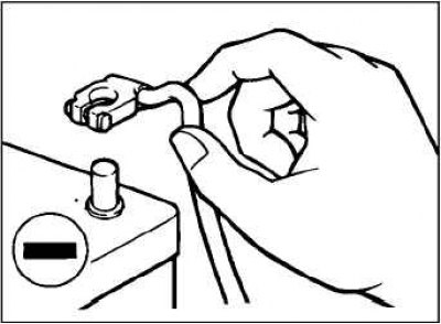
Caution! Before connecting or disconnecting the negative terminal from the battery, make sure the ignition and parking lights are off. (Otherwise, damage to the semiconductor elements may occur.).
Preparing the vehicle for diagnostic and control operations
The term "condition of the vehicle before the start of the control and diagnostic operations" means that the condition of the vehicle before the start of the test must meet the requirements specified below.
Coolant temperature: 80–90°C.
Headlights, electric cooling fan, and all other auxiliary power consumers must be switched off.
Manual transmission: in neutral position.
Automatic transmission: in "P" mode.
Temperature of sprayed water: no more than 82°C.
Testing with MUT-II device
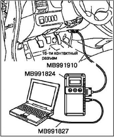
Connect the MUT-II device to the diagnostic connector as shown in the figure.
Caution: Before connecting or disconnecting the MUT-II, make sure the ignition key is turned to the "LOCK" ("OFF") position.
To prevent car fire
Incorrect installation of electrical or fuel system components may result in a fire. In order to ensure high quality and safety of the vehicle, it is necessary that the installation of any additional equipment, as well as repairs related to the electrical or fuel system, must be carried out in accordance with the "Repair Manual".