English Русский
Български
Беларускі
Український
Српски
Hrvatski
Română
Polski
Slovenský
Magyar
Articles Bookmark Contacts Sitemap   
Company Audi Company Ford Company Hyundai Company Kia Company Mazda Company Mercedes-Benz Company Nissan
MitsubishiMan.ru


Home Colt Lancer Galant L200 Outlander Pajero Others
Galant 6 and 7 (1987-1998) Galant 5 (1983-1989, petrol)

Removal and installation the heater and air conditioner control panel, adjusting the drive cables (Mitsubishi Galant 6)

  • Home
  • Galant
  • 6 (1987-1998)
  • Power unit
  • Cooling and heating
  • Removal and installation the heater and air conditioner control panel, adjusting the drive cables
0
Contents: Removal ⤓ Installation ⤓ Adjusting the drive cables ⤓
Warning! The vehicles covered in this manual are equipped with the Supplemental Restraint System (SRS), better known as the airbag. Before performing any work near the airbag assembly or steering column, always disable the system to avoid injury from accidental deployment - disconnect the negative battery cable first, then the positive cable, and wait at least two minutes before servicing components located near the directional overload sensors (see Chapter On-board electrical equipment). The insulation and connectors of the SRS circuit wiring are painted bright yellow. Do not connect any diagnostic equipment to this circuit!


Removal


1. Disconnect the negative cable from the battery.

Warning! If the car stereo system is equipped with a security code, make sure you have the correct combination to activate the audio system before disconnecting the battery!


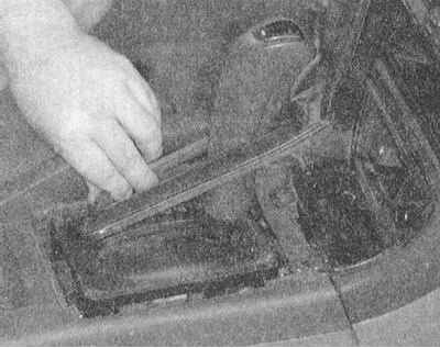
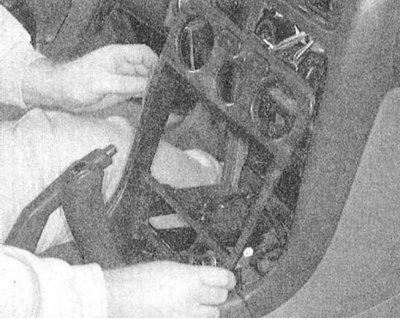
2. Release the clips and remove the center section of the instrument panel trim (see Chapter Body).
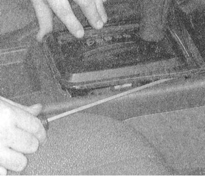


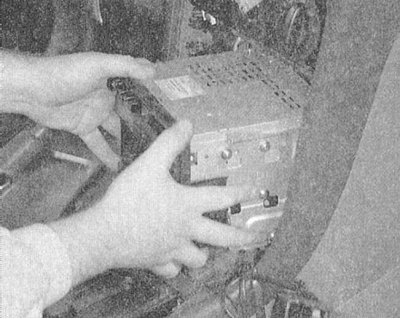
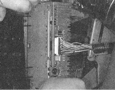
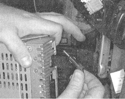
3. Remove the radio/CD player.


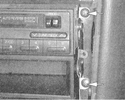
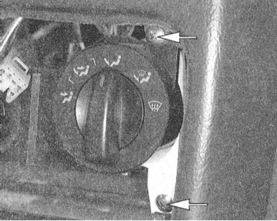
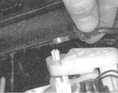
4. Remove the screws securing the heater/air conditioning control panel. Press the lever pin and disconnect the air distribution switch damper cable. Disconnect the other drive cables and wiring. Using needle-nose pliers, release the retainer and remove the control panel assembly from the vehicle.

(The article is reprinted from this source: «MITSUBISHIMAN»)
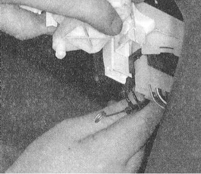


Installation


1. Move the temperature selection handle to the MAX HOT position (maximum heat).

2. Also move the drive lever of the distributing damper on the heater assembly to the MAX HOT position, then connect the drive cable to the lever pin.

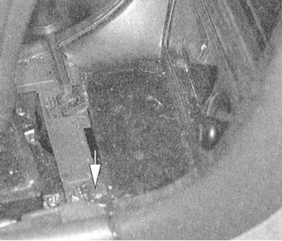
3. Pull the cable sheath in the direction indicated by the marker arrow to provide the assembly with the required slack, then secure the cable with the clamp.

4. Move the air flow direction selector handle to the windshield defroster (DEF) position. Set the drive lever of the corresponding damper on the heater assembly to the same position, then connect the drive cable to the lever pin.

5. Pull the cable sheath in the direction indicated by the marker arrow to provide the assembly with the required slack, then secure the cable with the clamp.

6. Set the air circulation mode selection lever on the control panel to the closed circulation mode. Set the drive lever of the corresponding damper on the heater assembly to the corresponding position. Connect the cable to the lever pin.

7. Pull the cable sheath in the direction indicated by the marker arrow to provide the assembly with the required slack, then secure the cable with the clamp.


8. Position the control assembly correctly on the instrument panel. Replace and tighten the mounting screws securely.

9. Install the retainer.

10. Connect the negative cable to the battery and check the air conditioning system for proper operation.

11. Reinstall the car radio/CD player.

12. Install the center section of the instrument panel trim (make sure all the provided fasteners are securely snapped into place). Screw in and tighten the mounting screws.

Adjusting the drive cables


1. Disconnect the negative cable from the battery.

Warning! If the car stereo system is equipped with a security code, make sure you have the correct combination to activate the audio system before disconnecting the battery!


2. Move the air distribution direction selector handle to the windshield blowing position. Move the corresponding damper lever all the way inward and connect the drive cable to it. Adjust the cable tension.

3. Move the air circulation mode selection lever to the closed circulation position. Move the damper flap inward as far as it will go and connect the cable to the drive lever. Adjust the tension as required.
This article is available at: russian, bulgarian, belarusian, ukrainian, serbian, croatian, romanian, polish, slovak, hungarian
This article was reviewed by: Dmitry Vasiliev
Share with friends:
◀ Previous
Galant 6 and 7: Cooling and heating
Next ▶

Checking and servicing heating and air conditioning systems
Removal and installation the heater heat exchanger
Replacing the electric motor of the heater fan drive
Checking and replacing the coolant temperature sensor unit
Removal and installation the water pump
 
Similar materials for other Mitsubishi models

➤ Scheme 6. Heater, air conditioner, instrument panel Mitsubishi Colt 4 and 5 (1991-2003)
➤ Heater and air conditioner control Mitsubishi Lancer 9 (2000-2007, petrol)
➤ Checking and adjusting the tension of auxiliary drive belts Mitsubishi L200 4 (2005-2014, diesel)
➤ Checking the power relay of the heater and air conditioner Mitsubishi Outlander 1 (2003-2008)
➤ Heater control panel and blower unit switch Mitsubishi Pajero 1 and 2 (1982-1999)
➤ Heater control panel and manual air conditioner switch Mitsubishi Carisma (1995-2004)
Link in different formats to this article
Comments and feedback from visitors
No comments yet


Add up two numbers 16 + 28


Galant 6 and 7 (1987-1998) 
  • General information
  • Introduction to guide
  • User manual
  • Driving and operation
  • Maintenance
  • Power unit
  • Dismantling the engine
  • Engine overhaul
  • Cooling and heating
  • Power and exhaust systems
  • Engine electrical equipment
  • Engine management systems
  • Transmission
  • Mechanical gearbox
  • Automatic gearbox
  • Clutch
  • Drive shafts and transfer case
  • Chassis and running gear
  • Brake system
  • Car suspension
  • Steering
  • Body and interior
  • Exterior (external elements)
  • Interior (internal elements)
  • Doors, locks and windows
  • Electrical equipment
  • Equipment and devices
  • Wiring diagrams Galant
  • Wiring diagrams Mirage
  • Wiring diagrams Diamante
Galant 5 (1983-1989, petrol) 
  • General information
  • Troubleshooting
  • Maintenance
  • Power unit
  • Engine repair
  • Engine overhaul
  • Cooling and heating
  • Fuel and exhaust system
  • Engine electrical equipment
  • Reducing exhaust toxicity
  • Transmission
  • Manual gearbox
  • Automatic gearbox
  • Clutch and drive shafts
  • Chassis and running gear
  • Brake system
  • Car suspension
  • Steering
  • Body and interior
  • Exterior (external elements)
  • Interior (internal elements)
  • Doors, locks and windows
  • Electrical equipment
  • Equipment and devices
  • Electrical diagrams
MitsubishiMan.ru © 2018–2026 • Mobile version • Articles about Mitsubishi • Contacts • Sitemap: EN BG BY UA RS HR RO PL SK HU • Site search • Bookmark
Colt 2 and 3 (1983-1993) · Colt 4 and 5 (1991-2003) · Colt 5 (1995-2003) · Lancer 3 and 5 (1984-1992) · Lancer 9 (2000-2007) · Galant 5 (1983-1989) · Galant 6 and 7 (1987-1998) · L200 4 (2005-2014) · Outlander 1 (2003-2008) · Pajero 1 and 2 (1982-1999) · Pajero 4 (2006-2021) · Carisma (1995-2004) · Space Star (1998-2005) ·
This resource sets cookies 🍪 to avoid bothering you with repeated data entry.