
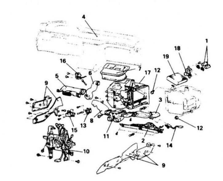
Installation details of the heater heat exchanger on Diamante models 1992÷1996. issue
1 - Branch pipes for connecting heating hoses; 2 - The right section of the lower trim of the instrument panel; 3 - Air supply hose to the passenger foot well; 4 - Instrument panel; 5 - Deflector of the air duct of the foot level; 6 - Sleeve A of the knee cooler; 7 - Assembly of the central air duct; 8 - Air supply hose to the driver's foot well; 9 - Front and rear central amplifiers; 10 - Assembly of the central mounting rack; 11 - Assembling the air flow distribution sleeve; 12 - Fasteners for the cooling unit; 13 - Power transistor; 14 - Coolant temperature sensor; 15 - Assembly of the damper motor for the formation of the temperature composition of the air; 16 - Damper motor of the outdoor air supply selector; 17 - Assembly of the heater; 18 - Overlay; 19 - Heat exchanger (radiator) heater
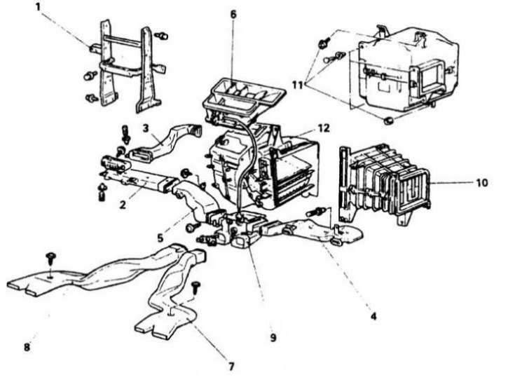
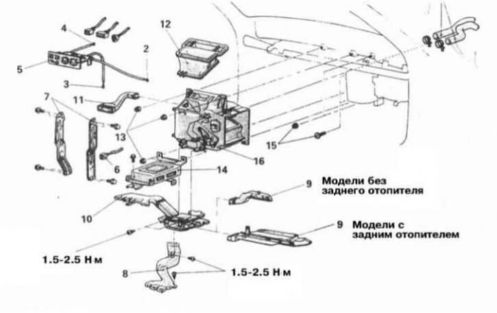
Installation details of the heater heat exchanger on Galant models 1990÷1993. issue
1 - Central mounting rack of the instrument panel; 2 - Deflector of the air duct of the foot level; 3 - Knee-level air duct; 4 - Air supply hose to the passenger foot well; 5 - Air supply hose to the driver's foot well; 6 - Central air duct; 7 - Rear heater air duct B; 8 - Rear heater air duct C; 9 - Air distributor of the lower level; 10 - Air duct (models without A/C); 11 - Evaporator fasteners (models with A/C); 12 - Heater assembly
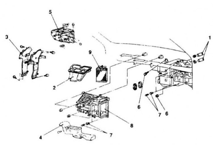
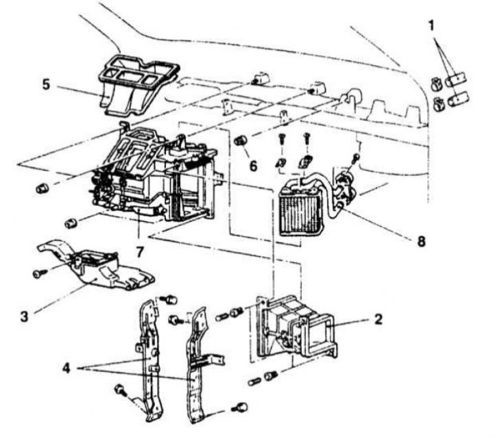
Installation details of the heater heat exchanger on Galant models 1994÷1998. issue
1 - Branch pipes for connecting heating hoses; 2 - Central ventilation sleeve; 3 - Central amplifier; 4 - Air distributor of the lower level; 5 - ECM support bracket; 6 - Fasteners for the evaporator; 7 - Clamps; 8 - Assembly of the heater; 9 - Heat exchanger (radiator) heater
Heat exchanger installation details on Galant 1999 and 2000 models. issue
1 - Belt lock controller (3.0 l models); 2 - Cover; 3 - Automatic compressor controller (models with A/C); Charging and discharging refrigerant (models with A/C); 4 - Tube of the refrigeration path (models with A/C); 5 - Expansion valve; 6 - O-rings (models with A/C); 7 - Evaporator; 8 - Drain hose (models with A/C); Draining and adding coolant; 9 - Heating hoses; 10 - Heater/cooler assembly; 11 - Heat exchanger heater
Heat exchanger installation details on Mirage models 1990÷1992. issue
1 - Heating hoses; 2 - Drive cable selection of the direction of air distribution; 3 - Drive cable for selecting the temperature regime; 4 - Drive cable for selecting the air circulation mode; 5 - Assembling the heater operation control; 6 - Wiring connector for the ECI control relay; 7 - Central mounting rack of the instrument panel; 8 - Sleeve A of the rear heater; 9 - Knee level air duct (models without rear heater) /transit duct (models with rear heater); 10 - Sleeve air supply to the foot wells; 11 - Knee-level air duct; 12 - Central air duct; 13 - Heater assembly fasteners; 14 - ELC-AT control unit; 15 - Fastener assembly of the evaporator; 16 - Heater assembly
Heat exchanger installation details on Mirage models 1993÷1996. issue
1 - Heating hoses; 2 - Connecting sleeve (models without A/C); 3 - Front air duct; 4 - Central amplifier; 5 - Central air duct; 6 - Fastener assembly of the evaporator (models with A/C); 7 - Assembly of the heater; 8 - Heat exchanger (radiator) heater
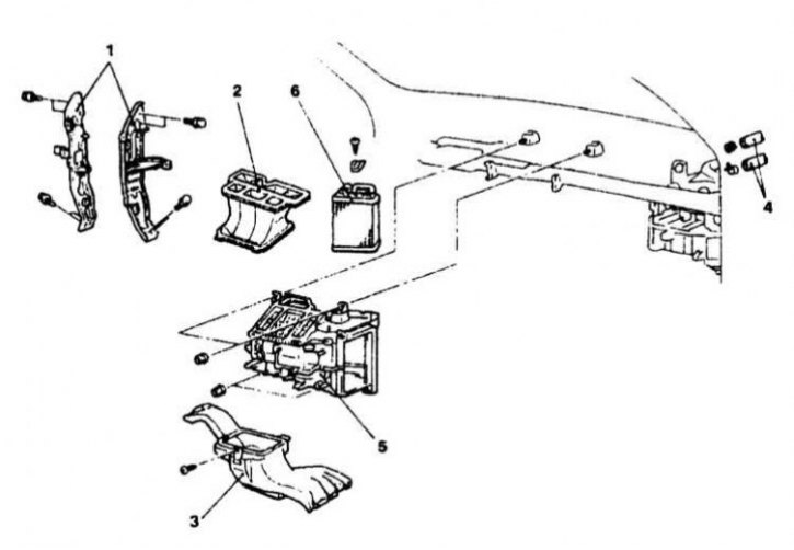
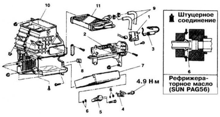
Heat exchanger installation details on Mirage models 1997÷2000. issue
1 - Central amplifier; 2 - Central air duct; 3 - Air distributor sleeve; 4 - Heating hoses; 5 - Assembly of the heater; 6 - Heat exchanger (radiator) heater
Warning! The vehicles covered in this manual are equipped with the SRS Supplemental Safety System, better known as the airbag. Before doing any work near the cushion or steering column assembly, be sure to turn off the system to avoid injury from accidental operation (see chapter Onboard electrical equipment). The insulation and connectors of the SRS wiring harness are bright yellow. Do not connect any diagnostic devices to this circuit!
The air conditioning system is constantly under high pressure. Never disconnect refrigeration lines or remove any system components without first discharging the system. The discharge of the air conditioning system must be carried out by an experienced specialist in a car service workshop. Always wear safety goggles when disconnecting refrigerant lines!
Do not allow antifreeze to come into contact with exposed areas of the body and painted surfaces of the car. Accidental splashes should be washed off immediately with plenty of water. Remember that antifreeze is a highly toxic liquid and getting it into the body, even in small quantities, is fraught with the most serious consequences (up to death). Never leave antifreeze stored in a loosely sealed container and clean up spilled coolant on the floor without delay. Remember that the sweet smell of antifreeze can attract the attention of children and animals. Consult any car service station about ways to dispose of used coolant. In many regions of the world, special points have been set up to receive various types of detention. Never drain old coolant down the drain and onto the ground! Recently, non-toxic grades of antifreeze have been developed, but they must also be disposed of in an organized manner.
Wait until the engine has completely cooled down before proceeding with the procedure.
Diamante Models
Removing
1. The details of installing the heater heat exchanger on Diamante models are shown in the illustrations.
2. Disconnect the negative cable from the battery.
Attention! If the stereo system installed in the car is equipped with a security code, before disconnecting the battery, make sure that you have the correct combination to activate the audio system! Disable SRS (see chapter Onboard electrical equipment).
3. Empty the cooling system and disconnect the water path rubber hoses from the heater heat exchanger (plug the open ends of the hoses immediately to prevent the risk of internal contamination of the cooling system).
4. Remove the right section of the lower furnish of the panel of devices.
5. Remove the passenger footwell air supply hose.
6. In order to dismantle the console assembly, remove the ashtray and unscrew the opened screw. Unscrew the remaining four, located on the sides of the assembly, the front screws and remove the console.
7. Remove the decorative caps, unscrew the exposed screws and remove the driver's knee support assembly with the support bracket.
8. Remove the steering column covers.
9. Remove the drummer of the glove box cover lock, the box assembly itself and its outer casing. Loosen the exposed screw.
10. Remove the radio trim panel and stereo
11. Remove assembly of management of functioning of systems of heating and air conditioning.
12. Remove the cup holder.
13. Remove the loudspeakers located from above on the panel of devices.
14. Remove facing of an instrument panel and a combination of devices.
15. Disconnect the speedometer drive cable from the transmission. Disconnect the adapter from the instrument cluster assembly, pull the cable inward slightly and remove the adapter.
16. Disconnect all wiring connected to the steering column. Turn out fixing bolts and lower a column down, having laid it on a driver's seat.
Attention! Be extremely careful - try not to allow any contact with the airbag module.
17. Remove a lamp of illumination of a ware box.
18. Turn out the remained fixing screws and remove the panel of devices.
19. Remove the driver's footwell air hose, knee-level coolant hose, and center air duct.
20. Remove the front and center amplifiers and the center mounting post.
21. Remove the air distribution sleeve assembly.
22. Disconnect all wiring connected to the heater assembly.
23. Turn out fixing screws, give nuts and remove assembly of a heater from the car.
24. Transfer the assembly to a workbench and remove the heat exchanger from the casing.
Installation
1. Thoroughly clean and dry the inside of the heater casing and install the heat exchanger and related components in it.
2. Install the heat exchanger assembly on the vehicle, tighten the fasteners. Follow the correct position of the casings of the heater and evaporator assemblies. Connect the electrical wiring to the components attached to the heater assembly.
3. Install the air distributor sleeve assembly. Install the front and rear amplifiers and the center mounting post.
4. Install the center air duct, knee cooler hose, and air supply hose to the driver's footwell.
5. Establish the panel of devices, screw in and tighten fixing screws.
6. Establish a lamp of illumination of a ware box.
7. Move to the working position and fix the steering column, connect the appropriate electrical wiring to it.
8. Connect the speedometer drive cable adapter to the instrument panel.
9. Establish a combination of devices and the panel of its facing.
10. Establish on the panel of devices the top loudspeakers.
11. Install the cup holder.
12. Install the air conditioning system operation control assembly.
13. Establish a stereosystem and the panel of facing of a radio receiver.
14. Screw in the screw located under assembly of a ware box.
15. Install glove box assembly.
16. Establish covers of a casing of a steering column.
17. Install the knee support bracket and the knee support itself. Screw in the fixing screws and plug them with decorative plugs.
18. Install the console assembly and ashtray.
19. Install the air supply hose to the passenger footwell.
20. Establish the right section of the lower furnish of the panel of devices.
21. Connect rubber hoses to the heater heat exchanger.
22. Fill the cooling system with coolant.
23. Connect the negative wire to the battery.
24. Check up serviceability of functioning of an automatic air conditioning system.
25. Check the elements of the heating path for signs of the development of coolant leaks.
Galant Models
Removing
1. Installation details of the heater heat exchanger on Galant models are shown in the illustrations.
2. Disconnect the negative cable from the battery.
Attention! If the stereo system installed in the car is equipped with a security code, before disconnecting the battery, make sure that you have the correct combination to activate the audio system! Disable SRS (see chapter Onboard electrical equipment).
3. With a cold engine, move the temperature selection lever to the FULL HOT position (maximum heating). Empty the cooling system.
4. Disconnect rubber hoses of a water path connected to branch pipes of the heat exchanger of a heater on a back bulkhead of an impellent compartment.
5. Remove the center console (see chapter Body).
6. Remove the heater cover.
7. Remove the steering wheel.
8. Remove a small cover from a casing of a steering column.
9. Remove section of the bottom finishing of the panel of devices.
10. Remove both sections of a casing of a steering column. Disconnect the wiring connected to the column.
11. Remove facing of an instrument panel.
12. Turn out screws of fastening of a combination of devices.
13. Release the instrument cluster from the mounting socket and disconnect the speedometer drive cable attachment from its rear side. Remove the instrument cluster.
14. Remove the floor console with subframe.
15. Disconnect and remove the air supply hoses to all vertical levels of the cabin.
16. Remove a ware box.
17. Remove the ashtray with support bracket (do not forget to disconnect the wiring from the cigarette lighter).
18. Remove facing of the panel of management of functioning of a heater.
19. Remove assembly of management of functioning of a heater and disconnect from it electroconducting.
20. Remove the right section of the bottom finishing of the panel of devices with a stretcher.
21. Remove the cover of the fuse box mounted on the left under the instrument panel. Loosen and remove the mounting block.
22. Remove panels of finishing of forward racks.
23. Remove the front sills of both front doors.
24. Release facing of a deflector of an obduv of a windshield, disconnect electroconducting from a photocell and remove facing and a lattice of a deflector.
25. Remove a lattice of a deflector of the central air duct.
26. Turn out bolts of fastening of an arm of a steering column to the panel of devices.
27. Remove the central reinforcement frame assembly. Loosen the right subframe bolts (try to remember their installation positions).
28. Turn out the remained fixing bolts and remove the panel of devices, having previously marked and having disconnected the corresponding electroconducting.
29. On models with an automatic air conditioning system, remove the heater installed before assembling (from below) power distribution control unit.
30. Remove the sleeve connecting the heater block to the evaporator casing (models with A/C) /heater fan assembly (models without A/C).
31. Carefully disconnect the vacuum hoses.
32. Remove the heater assembly from the vehicle and transfer it to a workbench.
33. Remove the cover from the water tap, disconnect the rods and remove the vacuum activator.
34. Release the clamps and remove the heat exchanger from the heater casing.
35. After removing the water tap, the heat exchanger can be replaced. Remove the plastic cover, loosen the mounting clamps, disconnect the hose and remove the tap.
Installation
1. Thoroughly clean and dry the inside of the heater casing and install the heat exchanger and water hose assembly into it (replace hose with clamps).
2. Install vacuum actuator and tie rod. Install the cover on the faucet assembly.
3. Install the heat exchanger assembly on the vehicle, tighten the fasteners.
4. Carefully connect the connector to the vacuum hose harness. Follow the correct connection of the hoses and the reliability of their attachment to their fittings.
5. Install the heating assembly cover and center console.
6. Install the sleeve connecting the heater and evaporator assemblies/heater fan assembly.
7. Install the power distribution unit, carefully connect the rods and rods.
8. Connect the cooling path hoses to the heat exchanger.
9. Install the instrument panel (proceed in the reverse order to the dismantling of the components).
10. Install the center console.
11. Establish casings of a steering column. Restore the original wiring connection.
12. Install the bottom trim center section.
13. Establish a small cover on a casing of a steering column.
14. Install the steering wheel.
15. Prime the cooling system.
16. Connect the negative wire to the battery.
17. Check up serviceability of functioning of an automatic air conditioning system.
18. Check the elements of the heating path for signs of the development of coolant leaks.
19. Connect the negative wire to the battery.
20. Check up serviceability of functioning of an automatic air conditioning system.
21. Check the elements of the heating path for signs of the development of coolant leaks.
Mirage Models
Removing
1. Heat exchanger installation details on Mirage models are shown in the illustrations.
2. Disconnect the negative cable from the battery.
Attention! If the stereo system installed in the car is equipped with a security code, before disconnecting the battery, make sure that you have the correct combination to activate the audio system!
3. Empty the cooling system. Disconnect heating hoses. Remove the decorative caps from the anchor bolts, the tray installed under the seats and the guide rings of the seat belts, give the fasteners, disconnect the wiring from the seat belt sensors-switches, then remove the seats.
4. Remove the coin box and storage box from the floor console assembly. Remove the power mirror switch assembly/plug.
Note. To release all of the listed components, use only a plastic tool!
5. Remove the back half of the console.
6. On models with a manual transmission, remove the gear lever handle.
7. Remove the front section of the console.
8. For fixing the instrument panel, pin-type plastic clips are used. To release such a latch, use a blunt punch to drown the central pin of the assembly, and then remove the latter from its seat.
Note. Do not press the pin with excessive force, as this may cause it to be pushed out from the opposite side of the retainer.
9. Remove forward overlays of thresholds of both doors.
10. Remove the ashtray.
11. Remove the central facing section of the instrument panel (radio trim).
12. Remove the sunglass case attached to the upper left corner of the instrument panel, as well as the side panel in which this case is mounted.
13. Remove the driver's knee brace and hood release handle.
14. Remove the top and bottom sections of a casing of a steering column.
15. Remove the radio.
16. Remove a ware box and a drummer of the lock of its cover.
17. Remove the bottom cover of the instrument panel and two small pieces of trim in the central part of the panel (pull them towards you).
18. Turn out the screw of fastening of assembly of management of functioning of a heater.
19. Remove facing of an instrument panel and take outside a combination of devices.
20. Remove the adapter for connecting the speedometer cable to the instrument cluster (the cable must first be disconnected from the transmission). Slightly pull the cable assembly towards you and rotate the nozzle slightly to release it.
21. Prying off with a flat-blade screwdriver, release the locking tabs and disconnect the connectors of the electrical wiring connected to the instrument cluster.
22. Using a plastic tool, remove the right speaker cover. Remove the loudspeaker and remove the side deflectors of the upper air ducts. Dismantle the clock. You should now be able to access the instrument panel mounting bolts.
23. Give a fixing nut, take a bolt and lower a steering column.
24. Turn out fixing bolts and remove assembly of the panel of devices.
25. Disconnect cables of management of modes of functioning of a heater from assembly of the last, then remove the control panel.
26. Disconnect the MFI control relay wiring.
27. Remove two stamped steel emphasis of the panel of devices.
28. Remove sleeves of air ducts.
29. Give nuts of fastening of assembly of a heater.
30. Remove the automatic transmission ELC control unit.
31. Give nuts and release clamps of fastening of assembly of the evaporator.
32. Pull the evaporator inside the passenger compartment, then remove the heater block.
Note. Be careful not to damage the connecting tubes.
33. Remove the cover installed on the heating pipes, then release the heat exchanger fasteners. Remove the heat exchanger from the heater housing - try not to damage the radiator lamellas and not cut your fingers on them.
Installation
1. Thoroughly clean and dry the inside of the heater casing and install the heat exchanger in it. Track reliability of a latch of clamps and a cover.
2. Install the evaporator and the ELC AT mounting block.
3. Install the heater assembly in its original place and connect the air duct sleeves.
4. Restore the original electrical wiring and control cable connections.
5. In reverse order of component removal, install the instrument panel assembly and console ().
6. Install the front seats.
7. Connect the negative cable to the battery.
8. Check up serviceability of functioning of an automatic air conditioning system.
9. Check the elements of the heating path for signs of the development of coolant leaks.