



Contents: Removal ⤓ Installation ⤓
The engine is lifted upwards using a crane or a pulley block. In cars produced before August 1988, the engine and gearbox were removed together; in cars of later production, they are removed separately.
Since some connections underneath the car need to be disconnected during removal, four stands and one jack are required to lift the car. The front fenders should be covered before installation to protect them from damage.
Depending on the year of manufacture and the model, the electrical wires, as well as the low-pressure or coolant hoses, may be routed differently in the engine compartment. Since it is impossible to give a detailed picture of each variant, it is recommended to mark the wires with adhesive tape if necessary before removing. The pictures show a carburetor engine manufactured from September 1988 onwards.
Removal
- Disconnect the ground cable from the battery.
Caution: This erases data in the electronic memory, such as the engine fault memory or the radio receiver code. Disconnect the battery only when the ignition is switched off, otherwise the injection device control unit may be damaged. Before disconnecting the battery, read the instructions in the "Radio receiver" and "Removing and installing the battery" sections.
- Remove the engine hood, see item 20.7.
- Drain the coolant, see p. 3.3.
- Remove the gearbox, see paragraph 12.1.
- Remove the radiator, see p. 3.6.
- Diesel engine: Drain engine oil, see paragraph 32.1.
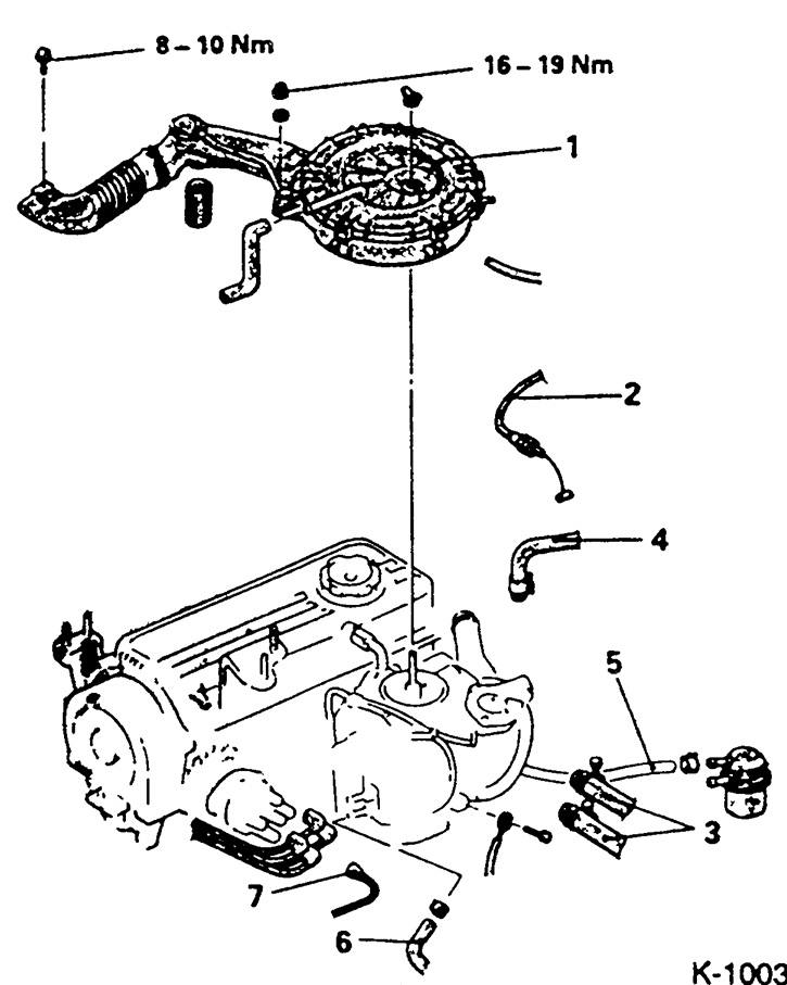
- Unscrew the air filter "1". Disconnect the warm air, low pressure and crankcase ventilation hoses.
- Disconnect the throttle cable "2" and move it to the side.
- Disconnect the two heater hoses "3" by first releasing and completely moving back the clamps.
- Disconnect the low pressure hose "4" of the brake booster from the suction pipe.
- Disconnect the supply hose "5" from the fuel pump and the fuel return hose "6" from the carburetor, having first loosened the clamps. When removing the hoses, place a rag underneath to collect any fuel that may spill out. If necessary, plug the hoses with suitable plugs. For example, screws with the appropriate thread diameter are suitable for this.
- Fuel injection engine (MPI): Unscrew the fuel supply hose connection plate from the jpy6bi distributor. Remove the sealing ring; replace the ring with a new one when installing.
- Vehicles produced before August 1990: Remove the high-tension wire from the center of the distributor cap between the ignition distributor and the ignition coil.
Note: To facilitate installation, mark the fuel hoses with adhesive tape.
Caution: The system is under pressure, so you must first release the pressure, see p. 8.3.

Disconnect all engine wiring:
- Secondary air valve connector "8".
- Idle speed increase valve connector "9".
- Cold start ignition timing valve connector "10".
- Thermal switch connector "11".
- Coolant temperature sensor connector "12".
- Coolant temperature sensor connector "13".
- Lambda probe (oxygen sensor) connector "14".
- Lambda valve connector-15-.
- Intake manifold heating connector "16"
- Throttle position sensor connector "17".
- Cars manufactured before August 1990. Distributor connector "18".
Disconnect the low pressure hose "19" from the carburetor.
Disconnect the low pressure hose from the socket "20".
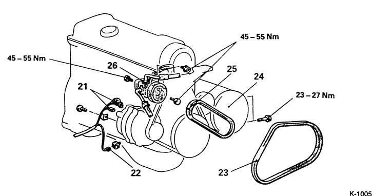
Disconnect the thick (B+) "21" and thin (D+) wires from the generator. Unscrew the wire fastener from the generator and release the wires from their fasteners at the engine support and the starter.
Disconnect connector "22" of the oil pressure switch sensor.
If available, remove the V-belt "23" of the air conditioner. Unscrew the 3 bolts securing the air conditioner compressor "24" to the bracket and put the compressor aside with the wires connected or hang it on a wire from the body.
Caution: Do not open the air conditioner refrigerant circuit. The refrigerant contains freon or frigen and can cause frostbite if it comes into contact with the skin. The engine can be removed without opening the refrigerant circuit.
Remove the V-belt of the servo pump "25", see p. 1.21.
Unscrew the servo pump "26" and put it aside with the hoses connected or hang it on a wire from the body.
Raise the car, see item 29.
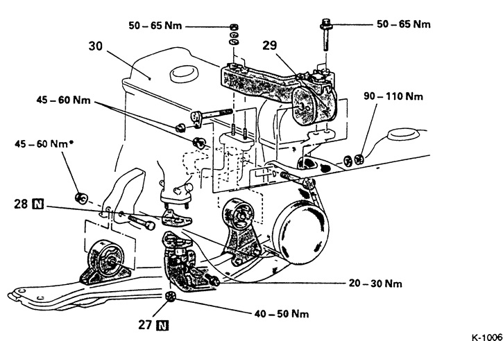
Unscrew the front muffler pipe "27". Lower the muffler and hang it on the wire by the body, see also item 10.
Remove gasket "28" and install a new one during installation.
Diesel engine: Loosen the hollow bolts securing the engine oil inlet and outlet pipes to the oil filter nipple. Remove the seals and replace them when installing.
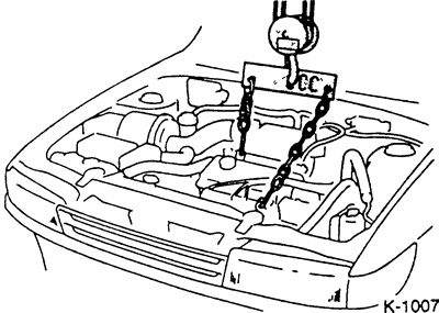
Raise the engine with a crane enough to relieve the engine mounts.
Unscrew the engine beam "29" (Fig. K-1006).
Remove the lower engine mounts.
Check that all wires and hoses are disconnected from the engine.
Slowly lift the engine with a crane.
Caution: Raise the engine carefully to avoid damaging the body.
Installation
Check engine mounts, oil and fuel hoses for cavities and cracks and replace if necessary.
Check the driven clutch disc for sufficient lining thickness and condition. If there is significant wear and tear and if the mileage is high, replace the clutch as a set. If noise is heard from the release bearing when pressing the clutch pedal, replace the bearing.
Check the release bearing for wear and replace if necessary, see p. 11.2.
Clean and coat the clutch release bearing and drive shaft tooth groove with a thin layer of grease (for example, MOS2 grease or MITSUBISHI 0101011 grease).
Carefully insert the engine into the engine compartment, being careful not to damage the drive shaft.
Install the engine on the supports and bolt it down, see Fig. K-1006.
Caution: Tighten the nut marked 1 by hand first. Only after the engine has been completely lowered should the nut be tightened to the specified tightening torque.
Disconnect the lifting device.
Place the muffler pipe with a new gasket on the exhaust manifold and secure with new nuts.
The source of the article is available at (mitsubishiman.ru)
Diesel engine: Tighten the engine oil feed and return pipes with new gaskets to the oil filter connection nipples with a torque of 45 Nm.
Install the air conditioning compressor.
Install the servo pump.
Install the V-belt, see p. 1.21.
Connect the connector to the oil pressure switch.
Connect the electrical wires to the generator.
Lower the car, see item 29. Fit all low pressure hoses, securing with clamps, see section "Removal".
Connect all electrical wires to the engine, see the "Removal" section.
Connect the fuel inlet and outlet hoses to the fuel pump and the carburetor and secure with clamps.
Caution: Do not mix up the fuel hoses.
Fuel injection engine: Connect and secure the fuel supply pipe with a new gasket.
Connect the throttle cable to the throttle body and to the heel, see item 6.7.
Connect the low pressure hose from the brake booster to the exhaust manifold and secure with a clamp.
Put on and secure the heater hoses with clamps.
Install the radiator, see p. 3.6. Install the gearbox, see paragraph 12.1.
Install the engine compartment hood, see item 20.7.
Diesel engine: Add engine oil.
Check the oil level in the engine and gearbox, top up if necessary, see paragraph 32.1.
Check the concentration of antifreeze in the coolant and top it up, see paragraph 32.1.
Adjust the throttle cable, see p. 6.8. Connect the ground cable to the battery.
Warm up the engine to normal operating coolant temperature.
Check the tightness of the hose connections.
Check the ignition timing, see p. 4.7.
Check the engine operation at idle speed, see paragraphs. 7.4/8.4.
Set the clock.
If you need to set the radio security code, see the section "Entering the radio code".