



Contents: Removal ⤓ Installation ⤓
Describes removal from a 1.5L engine with a fuel injection device manufactured after September 1988. A more detailed description of the process sequence for carburettor engines, especially with regard to disconnecting the electrical wiring, is contained in the section "Removal and installation the engine" Features for other engine types are given at the end of the section.
Depending on the year of manufacture and the composition of the equipment, the installation of electrical wires, as well as low-pressure and coolant hoses, can be carried out in the engine compartment in different ways. Since it is impossible to give a detailed picture for each option, it is recommended to mark the wires with adhesive tape before removal, if necessary.
Remove the cylinder head only when the engine is cool (ambient temperature). The intake and exhaust manifolds remain connected.
A defective cylinder head can be identified by one or more of the following signs:
- Loss of power.
- Coolant leak. White exhaust gases when engine is hot.
- Increased oil consumption.
- Coolant gets into the oil. The oil level does not fall, but rises. Gray color of engine oil, foam bubbles on the dipstick. The oil is liquid.
- Engine oil in coolant.
- The coolant is bubbling violently.
- Lack of compression in two adjacent cylinders.
Removal
Disconnect the ground cable from the battery. Caution: This will erase the data in the electronic memory, such as the engine fault memory or the radio receiver code. Disconnect the battery only when the ignition is switched off, otherwise the injection device control unit may be damaged. Before disconnecting the battery, read the instructions in the sections "Radio receiver" and "Removal and installation the battery".
Drain the coolant, see p. 3.3.
Disconnect and set aside the throttle cable.
Remove the crankcase ventilation hose between the cylinder head cover and the thick air intake hose.
Remove the air intake hose between the air filter and the thermostat housing. First, loosen and move the clamps back.
Remove the upper coolant hose from the thermostat housing. First, loosen and move the clamps back.
Remove the heater hose from the thermostat housing. First, release and move the clamp back.
Remove the coolant connecting hose between the throttle element and the coolant pipe branch. First, loosen and move back the clamps.
Disconnect the low pressure hose from the brake booster suction pipe.
Unscrew the mounting plate of the underwater fuel line from the distribution pipe. Remove the O-ring, install a new ring when installing. Caution: The system is under high pressure, so it is necessary to release the pressure first, see p. 8.3.
Remove the fuel drain pipe from the pressure regulator at the distribution pipe, having first released the clamps of the clamps. When removing, place a rag underneath to collect any fuel that may spill out. If necessary, plug the hoses with suitable plugs. For example, screws with the appropriate thread diameter are suitable for this. Put the fuel pipes aside, if necessary, secure them with wire to the body.
Remove all spark plug caps and remove spark plug wires from distributor cap.
Disconnect all electrical wiring from the cylinder head:
- Distributor connector -13/14-.
- Lambda probe connector "15".
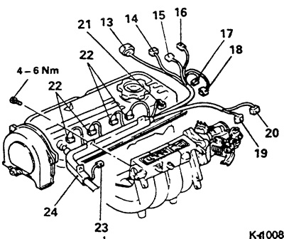
- Capacitor connector "16".
- Coolant temperature sensor connector "17".
- Coolant temperature sensor connector "18".
- Position sensor connector "19".
- Idle speed control connector "20".
- Throttle Position Sensor Connector "21"
- Injection valve connector "22".
- Noise filter connector.
Additionally for 84 hp engine:
- Detonation sensor connector.
- Power transistor connector.
- Ignition coil connector.
- Capacitor connector.
Release the "24" wire harness from the intake manifold and set it aside.
Note: The following symbols refer to Figure K-1009.
Remove the upper timing belt cover "25".
Remove the cylinder head cover "26" with the gasket "27". To facilitate subsequent installation, note the clamp fastenings on the cylinder head cover.
Set the engine to TDC, see p. 1.6.
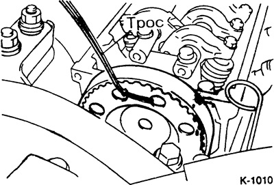
Secure the camshaft gear with a cable as shown in the figure. Loosen the mounting bolt, insert a large screwdriver or rod into the gear hole and rest it against the cylinder head to prevent the camshaft from turning. To avoid damaging the cylinder head, place a wooden shim under the screwdriver.
Caution: The timing belt remains on the camshaft gear. Make sure that the position of the belt on the gear does not change. When the camshaft gear is removed, the shaft must not be moved.
Raise the car, see item 29.
Unscrew the front muffler pipe "29". Lower the muffler and secure it to the body with wire, see also item 10.
Lower the car, see item 29.
Unscrew the intake manifold fitting.
Loosen the cylinder head bolts in the reverse order of tightening, i.e. from 10 to 1, see the "Installation" section. In this case, first unscrew all the bolts by 1/2 turn, and then unscrew them completely.
Check if all wires and hoses leading to the cylinder head have been removed.
Raise the cylinder head and place it on two wooden blocks.
Remove gasket "31" of the front muffler pipe, replace when installing
Remove the cylinder head gasket.
Installation
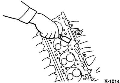
Before installation, carefully remove any remaining seals from the cylinder head and engine block using a suitable scraper. Make sure that no dirt gets into the holes in the block. Cover the holes with a rag.
Check if there is oil in the holes for the cylinder head bolts. If there is, be sure to remove it. To do this, insert a clean rag into the holes and blot the oil.
Caution: If there is oil in the holes, the engine block may be damaged when tightening the bolts.
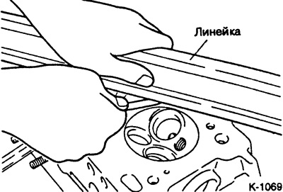
Check the cylinder head and engine block for misalignment using a steel ruler.
[The original material is posted on the website: MitsubishiMan.ru]
Check the tilt in various places of the cylinder head (engine block) using a steel ruler and a set of feeler gauges. The flatness should not exceed 0.2 mm (0.1 mm for the engine block).
Caution: When machining the cylinder head surfaces, the permissible minimum height must not be exceeded, see paragraph 1.17.
Be sure to replace the cylinder head gasket.
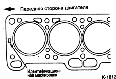
Apply the cylinder head gasket without sealant so as not to cover the holes. The identification marking must face up, towards the cylinder head.
Place a new gasket on the front muffler pipe.
Install the cylinder head. Make sure that the camshaft is in the TDC position of the 1st cylinder, see p. 1.6.
Tighten 10 cylinder head bolts with washers by hand. Cylinder head bolts must be replaced.
Caution: Tightening of cylinder head bolts must be carried out with special care. Before tightening, the accuracy of the torque wrench readings must be checked. Tightening of cylinder head bolts must be carried out on a cold engine.
Tighten the cylinder head bolts in 4 passes. Tighten the bolts in order from 1 to 10 in each pass.
Cylinder head bolt tightening sequence for 1.5L engine produced since August 1990.
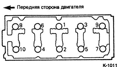
Engine 55 + 84 hp produced since January 1984.
- 1st pass: with a torque wrench of 20 Nm.
- 2nd pass: with a torque wrench at 40 Nm.
- 3rd pass: with a torque wrench at 60 Nm.
- 4th pass: with a torque wrench at 75 Nm.
Caution: Tightening the cylinder head bolts on a hot engine, during maintenance or after repairs is not permitted.
Secure the muffler with new nuts.
Place the toothed wheel with the toothed belt on the camshaft and secure it. Make sure that the camshaft and crankshaft are in the TDC position and that the position of the toothed belt on the toothed wheel is not knocked down, the TDC position see p. 1.6.
Install a new cylinder head cover gasket, put the cylinder head cover on and lightly tighten the bolts alternately.
Install the upper timing belt cover.
Tighten the intake manifold fitting with a torque of 25 Nm.
Check coolant, oil and low pressure hoses for porosity and tears, replace if necessary.
Install all low pressure hoses and tighten with clamps, see section "Removal".
Route the cable harness and secure it to the intake manifold.
Connect all electrical wires to the engine, see the "Removal" section.
Install and secure the fuel supply pipe with a new sealing ring. First, wet all the connection points with gasoline. When assembling, make sure not to squeeze or damage the sealing ring.
Place the fuel drain pipe onto the distribution pipe and secure with a clamp.
Connect the throttle cable to the throttle body and secure it to the intake manifold.
Install ignition wires, see p. 4.4.
Attach the low pressure hose of the brake booster and secure with a clamp.
Install the coolant and heater hoses and secure with clamps, see the "Removal" section.
Put on the air intake hose and secure it with a clamp.
Place the crankcase ventilation hose onto the air intake hose and onto the cylinder head cover.
Check the engine oil level and top up, see paragraph 32.1.
Adjust the throttle cable, see p. 6.8.
Connect the ground cable to the battery.
Bring the engine to operating temperature. To do this, warm up the engine while driving until the coolant reaches its normal operating temperature. Then drive another 5 km or so to ensure that the engine oil reaches a sufficient temperature.
Check for leaks at hose connection points.
Check the ignition timing, see p. 4.7.
Check the engine operation at idle speed, see paragraphs. 7.4/8.4.
Set the clock.
If you need to set a security code in the radio, see the section "Coding the radio".
Engine 124/136 hp.
Remove the radiator, see p. 3.6.
Remove the air flow meter connector from the air filter housing.
Remove the air filter.
Remove the semi-circular cylinder head cover seal from the front side.
Remove the timing belt.
Unscrew the tensioner from the intake manifold.
Installation should be carried out in reverse order.
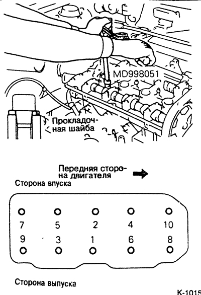
Cylinder Head Bolt Tightening Sequence
Caution: When tightening the cylinder head bolts, pay attention to the correct position of the spacer washers, see figure.
- 1st pass: with a torque wrench at 30 Nm.
- 2nd pass: with a torque wrench at 60 Nm.
- 3rd pass: with a torque wrench at 80 Nm.
- 4th pass: with a torque wrench of 100 Nm.
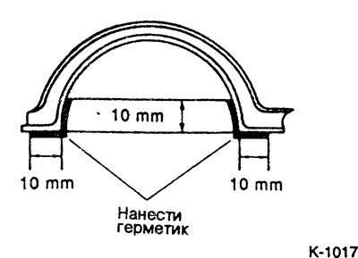
Insert the semicircular seal as shown in the following figure. First apply sealant, such as MITSUBISHI ЗМ-8660, to the contact surface of the cylinder head and the seal.

Coat the cylinder head cover gasket as shown in the following figure with a sealant, such as MITSUBISHI ЗМ-8660. Install the cylinder head cover and tighten very lightly (3 Nm).
Tightening forces:
- Tension: 50 Nm.
- Intake manifold nipple: 30 Nm.
Diesel engine
Disconnect the engine mount, see p. 1.4.
Remove the upper part of the intake manifold, see p. 1.10.
Loosen the fastening of the lower part of the intake manifold (nuts, 20 Nm).
Remove the spark plugs, see paragraph 32.1.
Set the engine to TDC position, see paragraph 1.13.
Remove the upper timing belt cover.
Place the camshaft gear with the timing belt on the lower timing belt cover. First, unscrew the camshaft gear, see paragraph 1.13.

Remove the injection tubes as a set. To do this, loosen the union nuts with 2 wrenches.
Caution: Do not damage the curvature of the injection tubes. After disconnecting the tubes, plug the holes with suitable plugs to prevent foreign objects and dirt from getting in.
Installation is carried out in reverse order.
Caution: The mating surfaces of the cylinder head and engine must not be machined.
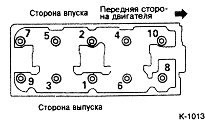
The tightening sequence of the cylinder head bolts is shown in Fig. K-1013. Cylinder head bolt tightening torque
- 1st pass: with torque wrench 30 Nm.
- 2nd pass: with torque wrench 60 Nm.
- 3rd pass: with torque wrench 90 Nm.
- 4th pass: with torque wrench 115 Nm.
Caution: When the camshaft is removed, the following additional work must be carried out:
Tighten the camshaft bearing cover bolts evenly in several passes and finally tighten to 20 Nm.
Tighten the rocker arm assembly to the bearing caps and rocker arm axle support to 30 Nm.
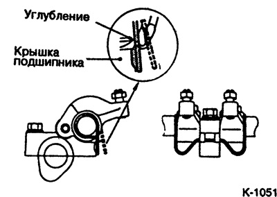
Insert the rocker arm springs into the recess of the bearing cap as shown in the figure.
Check valve clearances and adjust if necessary.
Tightening forces:
- Camshaft gear 100 Nm.
- Lower part of the intake manifold 20 Nm.