



Cylinder head mounting elements for 8-valve engine
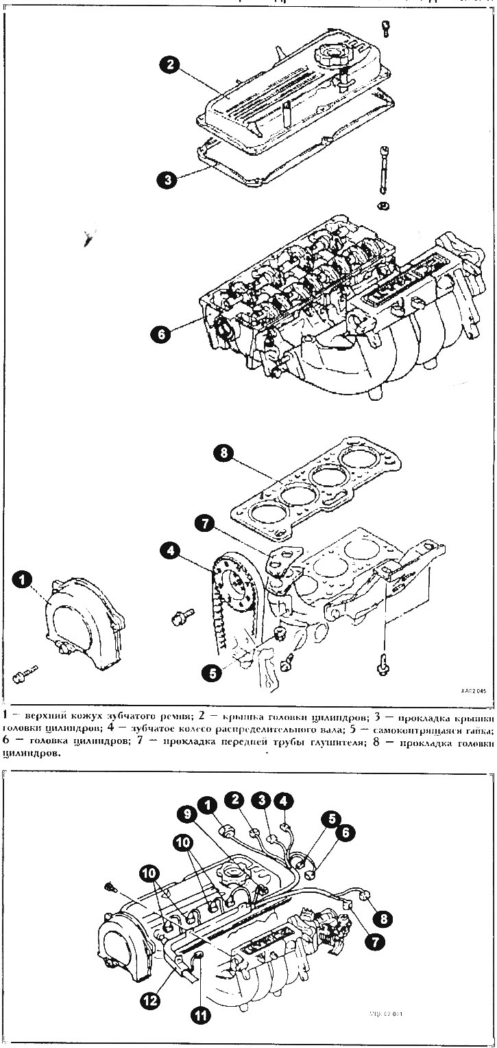
The cylinder head should only be removed when the engine is cool. The intake and exhaust manifolds remain connected.
A cylinder head malfunction is identified by one or more of the following signs:
- Low power.
- Coolant leak. White exhaust gases when engine is hot.
- High oil consumption.
- Coolant gets into the oil (oil level rises).
- Foam bubbles on the measuring rod (liquid oil, grey in colour).
- Presence of motor oil in the coolant.
- Lack of compression in two adjacent cylinders.
- The coolant is bubbling violently.
Removal
Disconnect the ground wire from the battery. Disconnect the battery with the ignition off, otherwise the injection device control unit may fail.
Drain the coolant.
Disconnect the throttle cable.
Remove the crankcase ventilation hose between the cylinder head cover and the thick air intake hose.
Remove the air intake hose between the air filter and the thermostat housing.
Disconnect the upper coolant hose from the thermostat housing.
Remove the heater hose from the thermostat housing.
The original was published on the website MITSUBISHIMAN.ru
Remove the coolant connecting hose between the throttle body and the coolant pipe branch.
Remove the low pressure hose from the brake booster suction pipe.
Unscrew the underwater fuel line mounting plate from the distribution tube. Remove the O-ring. Be sure to release the pressure.
After releasing the clamps, remove the fuel outlet pipe from the pressure regulator. If necessary, secure the fuel pipes to the body with wire.
Remove all spark plug boots and spark plug wires from the distributor cap.
Disconnect all electrical wiring from the cylinder head in the following sequence:
- Distributor connector (1,2) (see figure МЦК02 001)
- Lambda probe connector (3)
- Capacitor (4)
- Connector of coolant temperature sensor (5) and coolant temperature sensing element (6)
- Crankshaft position sensor (7)
- Idle air control valve connector (8) and then throttle position sensor (9)
- Injection valves (nozzles) (10)
For 84 hp engine additionally:
- Knock sensor connector
- Transistor
- Ignition coil and capacitor connector
Remove the wiring harness (12) from the intake manifold.
Remove the upper timing belt cover.
Remove the cylinder head cover with gasket and clamp fasteners on the cylinder head cover.
Set the engine to TDC.
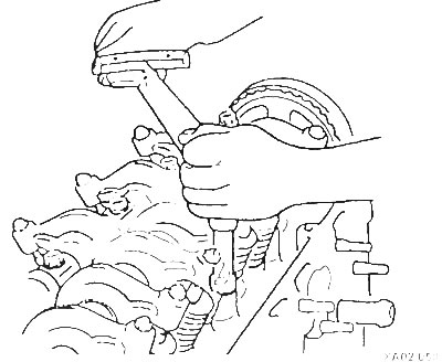
Lock the number one camshaft gear with a cable. Loosen the mounting bolt and insert a large screwdriver or rod into the gear hole and press it against the cylinder head to prevent the camshaft from turning. To avoid damaging the cylinder head, place a wooden shim under the screwdriver. Make sure that the belt position on the gear does not change.
Raise the car.
Unscrew the front muffler pipe and secure it to the body with wire.
Lower the car.
Unscrew the intake manifold fitting.
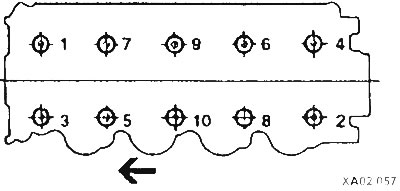
Loosen the cylinder head bolts in the order shown in the figure. In this case, first loosen all the bolts by 1/2 turn, and then completely unscrew them.
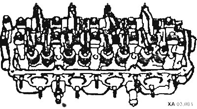
Check that all wires and hoses leading to the cylinder head are disconnected.
Lift the cylinder head and place it on two wooden blocks.
Remove the front muffler pipe gasket and the cylinder head gasket.
Installation
Before installing the cylinder head, remove any remaining seals from the cylinder head and cylinder block. To prevent dirt from getting into the block holes, cover the holes with a rag.
Check if there is oil in the cylinder head bolt holes. If there is, it must be removed by blotting the oil.
Check the flatness of the cylinder head and cylinder block with a steel ruler, as well as the distortion in various places of the cylinder head.
Replace the cylinder head gasket.
Position the cylinder head gasket without sealant so as not to cover the holes. The identification marking should face the cylinder head, upwards.
Place a new gasket on the front muffler pipe.
Install the cylinder head. Make sure that the camshaft is in the TDC position of the 1st cylinder.
Tighten the 10 cylinder head bolts with washers by hand. Replace the cylinder head bolts. Tighten the cylinder head bolts on a cold engine in 4 stages. Tighten the bolts in order from 1 to 10 at each stage.
Cylinder Head Bolt Tightening Sequence
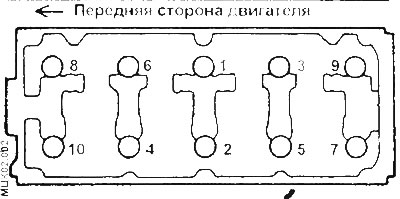
1st step: with a torque wrench of 20 Nm.
2nd step: with a 40 Nm torque wrench.
Step 3: With a 60 Nm torque wrench.
Step 4: Use a 75 Nm torque wrench.
Tighten the muffler with new nuts.
Place and secure the toothed wheel with the toothed belt on the camshaft. Make sure that the camshaft and crankshaft are in the TDC position and that the toothed belt position on the toothed wheel is not knocked off.
Install a new cylinder head cover gasket, put the cylinder head cover on and lightly tighten the bolts alternately.
Install the upper timing belt cover and tighten the intake manifold fitting to 25 Nm.
Check coolant, oil and low pressure hoses for porosity and tears.
Install all low pressure hoses and tighten with clamps.
Secure the cable harness to the intake manifold.
Connect the electrical wiring to the engine.
Wet all connection points with gasoline. Install and secure the fuel supply pipe with a new sealing ring. Be careful not to pinch or damage the sealing ring.
Connect the fuel return pipe to the distribution pipe and secure with a clamp.
Connect the throttle cable to the throttle body and secure it to the intake manifold.
Install the ignition wires.
Install the low pressure hose of the brake booster and the coolant and heater hoses and secure with clamps.
Connect the air intake hose and secure with a clamp.
Place the crankcase ventilation hose onto the air intake hose and onto the cylinder head cover.
Check the engine oil level.
Adjust the throttle cable.
Connect the ground wire to the battery.
Warm up the engine to operating temperature.
Check the hose connections for leaks.
Check the ignition timing.
Check the engine operation at idle speed.
Set the clock.