
Removing
Relieve residual pressure from the high pressure fuel line.
Drain the coolant.
Drain the engine oil.
Remove the air filter assembly.
Disconnect the accelerator pedal cable.
Remove the exhaust manifold.
Remove the top timing belt cover.
Remove the coolant inlet pipe and thermostat housing assembly.
Remove the cylinder head cover.
Removing the camshaft sprocket
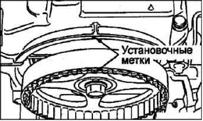
Turn the crankshaft clockwise until the timing marks on the camshaft sprocket and crankshaft sprocket are aligned with the corresponding timing marks, and set the No. 1 cylinder piston to TDC on the compression stroke.
Attention! Turn the crankshaft only clockwise.
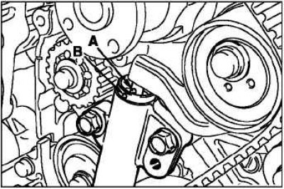
Remove the plug and screw the special rod into the hole of the attachment mounting bracket so that it rests against the groove on the tensioner arm.
Slowly screw in the special rod, aligning the hole «IN» on the body of the automatic tensioner with a hole «A» on the tensioner rod.
Attention! Screw in the special rod in increments of no more than 30°per second. If the rod is turned at full speed immediately, it may be deformed due to the difficult movement of the tensioner rod.
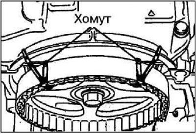
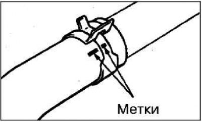
Fix the timing belt to the camshaft sprocket in the position shown in the illustration using a band or wire.
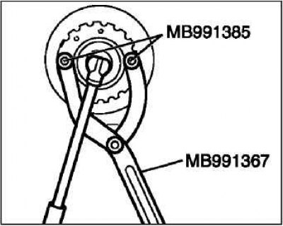
Secure the camshaft sprocket against rotation with a special holder and bolts.
Loosen the camshaft sprocket bolt.
Attention! Do not rotate the crankshaft after removing the camshaft sprocket.
Before removal, apply installation marks of the original position of the radiator hose and clamp. Disconnect the upper radiator hose.
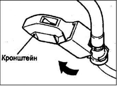
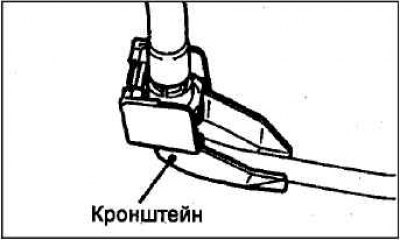
On 4G69 series engines, before disconnecting the high pressure fuel hose, remove its bracket.
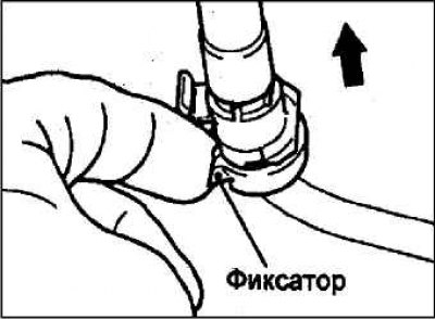
Remove the fuel hose clamp and pull it in the direction of the arrow in the figure.
Note. If the high pressure hose retainer has been released, reinstall it after disconnecting the hose.
Removing the power steering pump assembly with bracket
Remove the power steering pump assembly with bracket along with hoses connected to it.
Note. Tie the removed power steering pump assembly with bracket and hoses with wire and place it in a place where it will not interfere with the removal and installation of the cylinder head assembly.
Removing the cylinder head
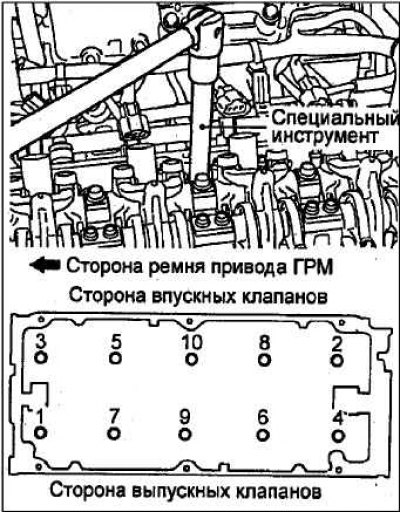
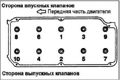
Loosen the bolts in 2 or 3 steps in the sequence shown in the figure, and then remove the cylinder head assembly.
Attention! When loosening the cylinder head bolts, be careful not to damage or deform the spark plug guide tubes as they are not supplied separately.
Installing the cylinder head gasket
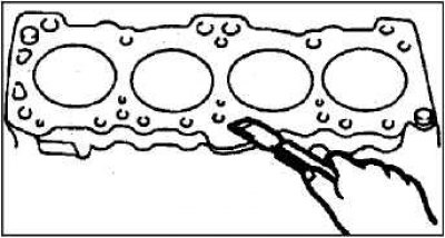
Using a special scraper, remove the remnants of the old cylinder head gasket from the cylinder block.
Attention! When carrying out this operation, do not allow gasket material or other foreign particles to enter the channels of the cooling system and lubrication system.
Degrease adjacent gasket surfaces.
At installation check up coincidence of all openings on a lining and a head of cylinders.
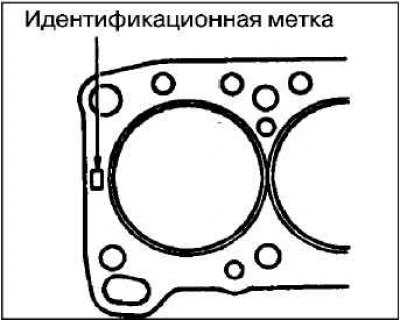
Verify that the correct engine identification mark is on the new cylinder head gasket.
Lay the cylinder head gasket on the cylinder block with the identification mark facing up, so that it is located on the side of the exhaust valves.
When installing the cylinder head bolts, make sure the length «A» of each bolt is within the allowable value. If length «A» exceeds the limit value, the bolts must be replaced.
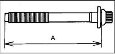
Limit value «A»: 99.4 mm.
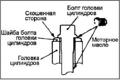
Lubricate the threads and washers of the cylinder head bolts with a thin layer of engine oil.
Note. If the cylinder head bolt washer has been replaced, install it with the chamfered side up as shown.
 |  |
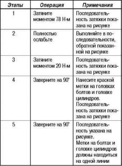
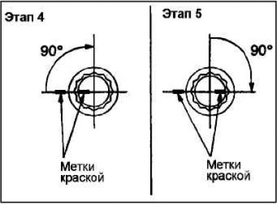
Tighten the bolts according to the procedure below.
Note. Always turn the bolt to a strict 90°angle. Otherwise, the cylinder head bolt may be loosened (the reliability of the gas joint will not be ensured).
Note. If the bolt is turned more than 90°, loosen it completely and repeat all operations starting from point 1.
 |  |
High pressure fuel hose installation
Lubricate the O-ring with a little fresh engine oil.
Attention! Do not allow oil to enter the fuel manifold.
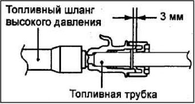
Slightly turning the fuel hose flange to the right or left, carefully insert it into the fuel manifold to prevent damage to the gasket. After installation, check that the hose turns smoothly in the fuel manifold.
If the hose flange sticks when turning, the cause may be a damaged O-ring. Detach the flange (complete with hose) from the fuel rail and check the gasket for damage, then reinsert it and check for smooth rotation.
Connecting the Upper Radiator Hose
When connecting the upper radiator hose, put it on the protrusion of the branch pipe until it stops, then tighten the clamp.
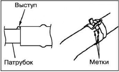
The hose clamp should always be installed in the position in which the clamp was installed when removed. Therefore, before installing the clamp, align the alignment marks on the hose clamp and the radiator hose, then connect it.
Camshaft sprocket installation
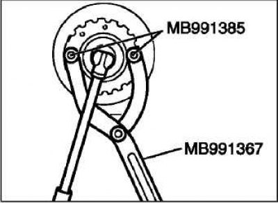
Secure the camshaft sprocket against rotation with a special fork holder and special bolts.
Wrap a bolt of fastening of an asterisk of a camshaft the nominal moment.
Tightening torque: 89±9 Nm.
After completing the installation of the parts, perform the following operations:
On 4G69 series engines, install the cylinder head cover.
Install the coolant inlet pipe and thermostat housing assembly.
Install the timing belt top cover.
Install the exhaust manifold.
On 4G69 series engines, connect the accelerator pedal cable.
Install the air filter assembly.
Fill with coolant and engine oil.
Adjust the tension of the accessory drive belt.
Adjust the accelerator pedal cable.