



Contents: Removal the piston and connecting rod ⤓ Checking the piston and piston pin ⤓ Piston rings ⤓ Checking the condition of the…⤓ Checking the clearance in the…⤓ Measuring the clearance in a…⤓ Checking the connecting rod ⤓ Selection of piston pin ⤓ Replacing the piston pin ⤓ Preparing a special tool ⤓
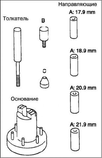
Note: Work on disassembling and assembling the connecting rod and piston group is performed using a special tool (a set for assembling and disassembling piston assemblies).
 |  |
Removal the piston and connecting rod
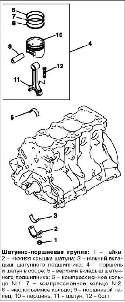
Loosen the nut, remove the connecting rod cover and remove the piston and connecting rod from the cylinder.
Caution! When removing the piston with the connecting rod assembly, do not damage the cylinder surface and the crankshaft journal with the connecting rod.
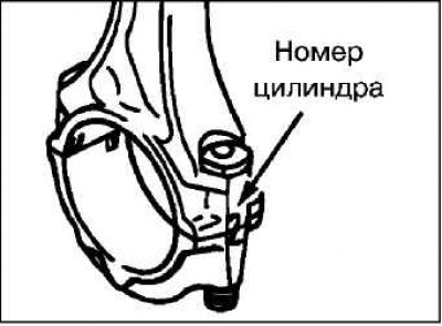
Mark the cylinder number on the side of the connecting rod to facilitate subsequent assembly.
Place the removed parts (connecting rods, pistons, liners, etc.) in the order they correspond to the cylinder numbers, for correct subsequent assembly.
Checking the piston and piston pin
Attention! The piston and piston pin are replaced as a repair kit.
Carefully inspect the piston, replace it if there are scratches or scoring on the working surfaces (especially on the thrust surfaces).
Press the piston pin into the piston hole using your thumb. You should feel resistance. Replace the pin if it fits into the hole easily or there is noticeable play.
Piston rings
Attention! Old piston rings are replaced with new ones if a new piston is installed.
Check the piston rings for damage, breaks or noticeable wear.
Measure the gap between the piston ring and the piston groove. If the gap exceeds the permissible value, replace the ring, the piston, or both parts together.
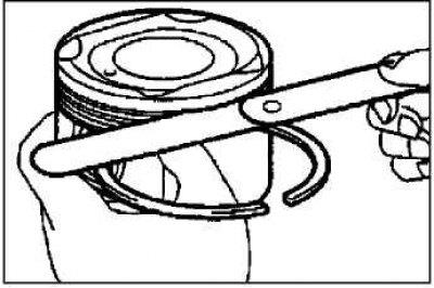
Note: Before taking measurements, remove carbon deposits from all piston grooves.
Note: Measure the gap between the ring and the piston groove along the entire circumference of the ring.
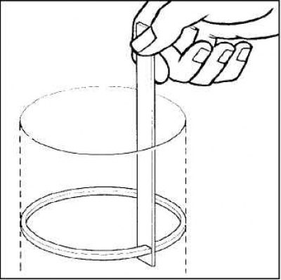
Install the piston ring into the cylinder bore. Move the ring with the piston as shown in the figure so that the ring is installed at a right angle to the cylinder wall generator.
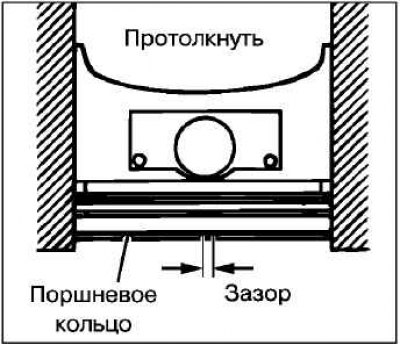
Measure the gap in the ring lock, if the gap is greater than the permissible value (see the corresponding table), replace the ring.
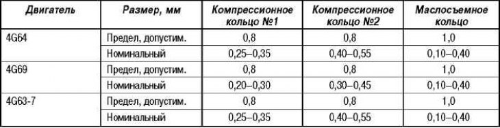
Checking the clearance between the compression ring and the groove for it (mm)

Checking the piston ring gap (mm)
Checking the condition of the connecting rod bearing shells
Inspect the surface condition of the connecting rod bearing shell for uneven contact, scratches and scoring. If defects are present, replace the connecting rod bearing shells.
If the defects are significant, check the corresponding crankshaft journals. If there are defects on the crankshaft journals, replace the crankshaft.
Checking the clearance in the connecting rod bearing
Measure the inside diameter of the connecting rod bearing and the outside diameter of the crankshaft journal, then determine the clearance of the connecting rod bearing. A plastic gauge is usually used to measure the clearance of the connecting rod bearing.
Nominal outside diameter of crankshaft connecting rod journal: 45.0 mm.
If the oil clearance exceeds the maximum allowable value, replace the connecting rod bearing shells, the crankshaft, or both.
Measuring the clearance in a connecting rod bearing using a plastic gauge
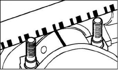
Clean the crankshaft journals and bearings from oil and dirt.
Cut a piece of plastic gauge the same length as the bearing width and place it parallel to the journal axis away from the oil passage hole.
Install the bearing shell and connecting rod cap and tighten the nuts.
Note: Do not turn the crankshaft.
Remove the cover and use the scale printed on the gauge packaging to determine the bearing clearance.
Clearance in connecting rod bearing
- Nominal: 0.02–0.05 mm.
- Maximum permissible: 0.10 mm.
Checking the connecting rod
Install the connecting rod small end bushing and piston pin into the connecting rod if they were removed.
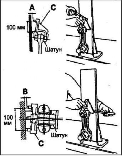
Using a special connecting rod test stand "C" and a flat feeler gauge, check the bending and twisting of the connecting rod as shown in the figure.
Maximum permissible value (per 100 mm of length):
- bending: 0.05 mm;
- twist: 0.10 mm.
Attention! Install the connecting rod in a special stand "C" together with the installed upper and lower connecting rod bearing shells.
Tighten the connecting rod cap bolts according to the specific procedure.
Connecting rod length: 149.9–150.0 mm, connecting rod length is the distance between the centers of the upper and lower heads of the connecting rod.
If the connecting rod bending or twisting exceeds the maximum allowable value, replace the connecting rod assembly with the cap.
Selection of piston pin
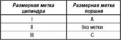 | 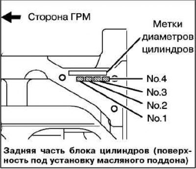 |
Caution! If the engine cylinders have not been machined, when replacing the piston, select it so that the mark on the top corresponds to the cylinder size mark on the cylinder block according to the table provided.
Replacing the piston pin
Note: Work on disassembling and assembling the connecting rod and piston group is performed using a special tool (a set for assembling and disassembling piston assemblies).
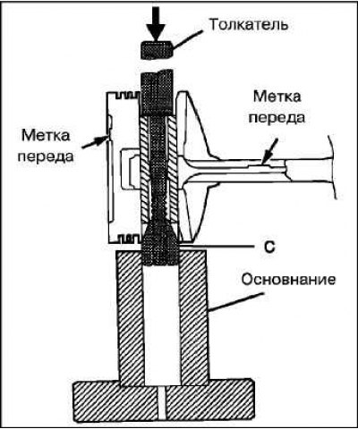
Insert the push rod into the piston from the side of the "front" mark (in the form of an arrow) applied to the bottom of the piston.
Install the piston and connecting rod on the base with the "front" marks facing up, as shown in the figure.
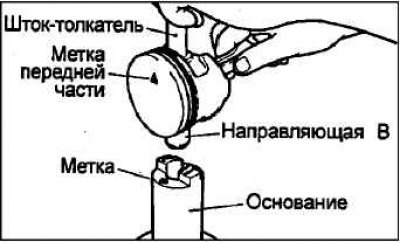
Use a press to remove the piston pin.
Note: To facilitate further assembly, keep disassembled parts separate from other similar parts.
Preparing a special tool
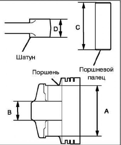
Measure the following values:
- "A" – length of the hole for the piston pin;
- "B" is the distance between the piston bosses;
- "C" – piston pin length;
- "D" – width of the upper connecting rod head.
Determine the value of "L" using the method described below.
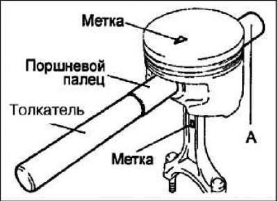
Place the piston pin on the push rod and screw the guide sleeve "A" onto the end of the rod.
Place the piston and connecting rod together with the "front" marks facing up on the base of the device. Lubricate the piston pin surface with a thin layer of motor oil. Install the unit (push rod with piston pin and guide sleeve "A" in assembly) with the sleeve in the combined hole of the piston and connecting rod (for the piston pin) on the side of the "front" mark.
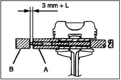
Screw the guide sleeve "B" into the guide sleeve "A" so that a distance equal to the value "L" measured in subparagraph (e) + 3 mm is formed between these guide sleeves.
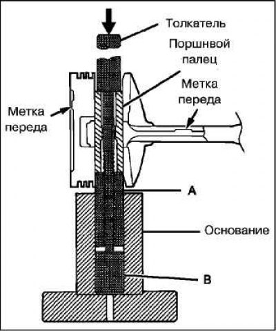
Place the piston and connecting rod together with the "front" marks facing up on the base of the device, n) Press the push rod with a press to install the piston pin. If the force developed during pressing is less than the nominal value, replace the piston with the piston pin assembly and/or the connecting rod.
- Standard pressing force: 7350–17,200 N.
- Nominal outside diameter of piston pin: 22.0 mm.
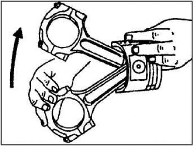
Check that after assembly the piston can swing freely on the connecting rod when moved in the direction of the arrow.