



Contents: Removal the flange at the top of the…⤓ The order of installation of rings…⤓ Piston orientation on diesel ⤓ Piston orientation on V6 engines ⤓ Removal ⤓ Examination ⤓ Installation ⤓
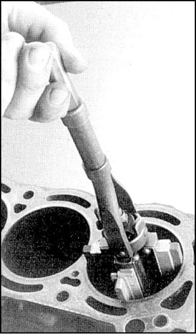
Removal the flange at the top of the cylinder
The order of installation of rings on a diesel engine
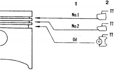
1. Installation procedure
2. Marking
Piston orientation on diesel
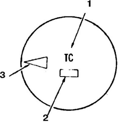
1. Marking; 2. Size group stamp; 3. Arrow (directed forward)
Piston orientation on V6 engines
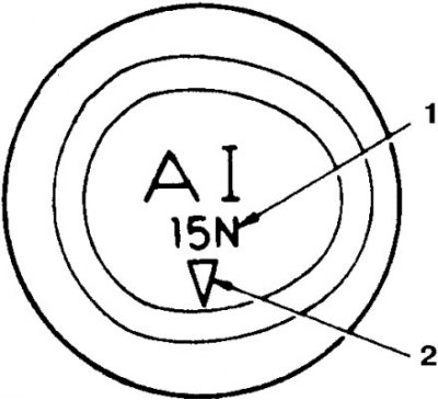
1. Marking
2. Arrow (directed forward)
Removal
1. The piston with the connecting rod is pushed out through the top of the cylinder block after unscrewing the connecting rod cap bolts and removing the flange at the top of the cylinder. The connecting rods are marked according to the cylinder number. Connecting rod caps should be numbered before removal. Remove the rings using a special tool.
2. Clean the pistons by removing carbon deposits.
Examination
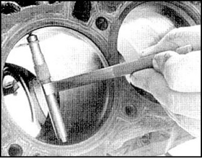
1. Check the ovality and taper of the cylinders. To do this, check the cylinder diameter by measuring it in the longitudinal and transverse directions relative to the engine axis, in three places - directly under the flange, at the bottom of the cylinder and in the middle.
2. If the taper and ovality are within normal limits, then hone the cylinders. Otherwise, the cylinders should be bored and the pistons and rings replaced with repair ones (these procedures are performed in a car service center).
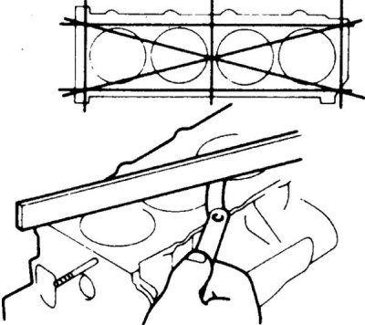
3. Check the deformation of the cylinder block split plane. If the deviation from the plane is more than 0.1 mm, then grind the block.
4. Check the condition of the piston. The presence of cracks near the skirt, as well as deep visible scratches and grooves on the side surface is not allowed.
5. Measure the piston diameter in the direction perpendicular to the piston pin axis at skirt level. Determine the clearance between the piston and the cylinder. If the gap is higher than normal, replace the piston. If the clearance is not within the norm when replacing the piston, bore the cylinders and replace the pistons with repair ones.
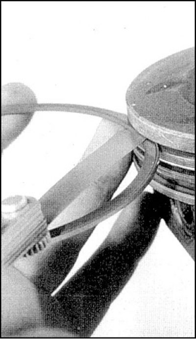
6. Check the clearance between the compression rings and the groove in the piston. If the gap is slightly higher than normal, the rings should be replaced.
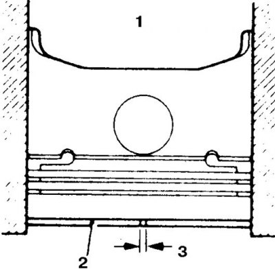
7. Check the gaps in the piston ring joints by pushing the ring with the piston (1 – piston, 2 – ring, 3 – gap). The gaps should be within the norm at 15 mm from the lower edge of the cylinder.
8. Check the condition of the connecting rods by visual inspection. The presence of deformations, curvature of the arc bed under the liner in the lower part and non-parallelism of the connecting rod cover mounting studs are not allowed. There should be no noticeable play in the piston pin in the connecting rod (the pin is pressed into the connecting rod). The damaged connecting rod is straightened in a car service or replaced.
Installation
Piston ring joint arrangement
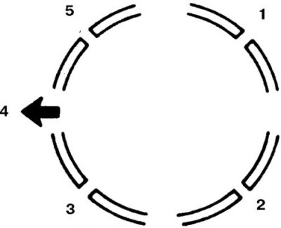
1. Upper compression; 2. Upper disc of oil scraper ring; 3. Lower compression and oil scraper ring expander; 4. To the front of the engine; 5. Lower disc of oil scraper ring
1. New rings must match the piston size group. All gaps in the rings must be checked and meet the standard.
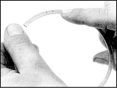
2. Install the rings in the following order: oil scraper ring, lower compression ring, upper compression ring (this ring is installed only with the help of an expander). The mark on the ring should face up.
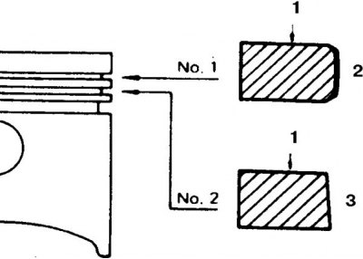
3. The sections of the upper and lower compression rings differ (1 – N and T markings, 2 – rounded profile, 3 – conical profile).
4. Arrange the piston ring joints.
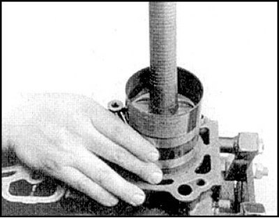
5. Lubricate the cylinder, compress the rings with a device, correctly orient and insert the piston into the cylinder, complete with rings, connecting rod and upper bearing. Install the lower insert into the lid and secure the lid with nuts. Repeat the procedure for the remaining connecting rods, turning the crankshaft. Tighten the nuts to the specified torque in 2-3 stages.
6. Install all removed parts (if the repair was carried out without removing the engine).