



Note: Before removing the pistons/connecting rods, remove the cylinder head and oil pan as described in the relevant sections part A Chapter 2.
1. Check with your fingernails to see if you can feel a rib at the top of the piston ring travel (approximately 6 mm below the top edge of each cylinder). If a rib has formed as a result of carbon deposits or cylinder wear, it must be completely removed with a special tool (see illustration). Follow the manufacturer's instructions supplied with the tool. Failure to remove the rib before removing the piston/connecting rod may damage the piston.
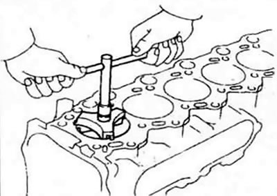
13.1 A special tool is required to remove the flange from the top edge of each cylinder - do this before removing the pistons.
2. After removing the flange, turn the engine over with the crankshaft facing up.
3. Before removing the connecting rods, check the end play using a flat feeler gauge. Insert such a feeler gauge between the first connecting rod and the crankshaft web until there is no play (see illustration). The end play is equal to the thickness of the inserted feeler gauge(s). If the end play exceeds the permissible operating limit specified in the specification, then new connecting rods must be installed. When installing new connecting rods (or a new crankshaft), the end play may fall below the minimum limit specified in the specification (in this case, the connecting rods must be ground down until the required play is restored - consult a machine shop). Repeat the procedure for the remaining connecting rods.
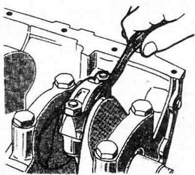
13.3. Check the clearance between the connecting rods and the crankshaft with a flat feeler gauge as shown in the illustration
4. Check for identification marks on the connecting rods and caps. If there are no marks, number them with a center punch with the appropriate numbers (1, 2, 3, etc. depending on the engine type and cylinder number).
5. Loosen each connecting rod cap nut 1/2 turn at a time until they can be removed by hand. Remove connecting rod cap #1 and bearing shell. Do not allow the shell to fall out of the cap.
6. Place a short piece of plastic or rubber hose over the connecting rod bolts to protect the crankshaft journals and cylinder wall while removing the piston.
7. Remove the bearing shell and push the connecting rod/piston out through the upper cylinder axle. Tap the wooden handle of the hammer into the bearing surface of the upper connecting rod shell. If resistance is felt, check again for a rib at the top of the cylinder.
8. Repeat the procedure for the remaining cylinders.
9. Once removed, install the connecting rod caps and bearing shells in their old locations and tighten the cap nuts with finger force. Leaving the old bearing shells in place until assembly will protect the bearing surfaces from accidental damage.
10. Do not separate the pistons from the connecting rods (for more information, see section 18).