



Contents: Cleaning ⤓ Examination ⤓ Cylinder head ⤓ Valves ⤓ Valve train elements ⤓ Valve rocker arm components ⤓ Injector valves ⤓
1. Completely clean the cylinder head and valve train components, then perform a thorough inspection of the components to determine the amount of valve reconditioning work that must be performed during the engine overhaul.
Note: If the engine has overheated, the cylinder head is most likely warped (see point 12).
Cleaning
2. Remove all traces of old gasket and sealant from the cylinder head gasket and the sealing surfaces of the intake and exhaust manifolds. Be careful not to scratch the cylinder head. A special gasket remover is commercially available that softens the gasket and makes it easier to remove.
3. Remove scale from the cooling channels.
4. Remove plaque from all canals using a soft wire brush.
5. Using appropriate taps, clean all threaded holes from corrosion and adhesive. If possible, blow out all holes with compressed air after this operation.
Warning: When using compressed air, wear safety glasses!
6. Clean the valve adjuster threads in the rocker arms with a wire brush.
7. Clean the cylinder head with solvent and dry it completely. Compressed air can speed up the drying process and ensure that all holes and cavities are clean.
Note: There are commercially available chemical carbon removers that may be useful for cleaning the cylinder head and valve train components. These products are very caustic and require great care when used. Follow the instructions on the packaging.
8. Clean the rocker arms, springs, wave washers and axles with solvent and dry them completely (do not mix them up when cleaning). Compressed air will speed up the drying process and ensure that all passages are clean.
9. Clean all valve springs, valve seats, keepers and valve spring retainers in solvent and dry them completely. To avoid mixing up parts, work on only one valve at a time.
10. File off any hard deposits that may have formed on the valves, then remove the deposits from the valve heads and stems with a mechanical wire brush. Be careful not to mix up the valve parts.
Examination
Note: Before deciding whether to take the engine to a machine shop, be sure to perform all of the following inspection procedures. Make a list of items that require attention. The procedures for inspecting the tappets and rocker arms, as well as the camshaft, are described in parts A.
Cylinder head
11. Very carefully inspect the cylinder head for cracks, visible signs of coolant leakage and other damage. If cracks are found, consult a mechanical workshop about the possibility of repair. If repair is not possible, you must purchase a new cylinder head.
12. Using a flat block and feeler gauge, measure the curvature of the cylinder head sealing surface. If the curvature exceeds the specification limit, it can be machined in a machine shop.
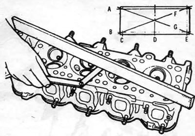
10.12. Check the straightness of the cylinder head sealing surfaces by inserting a flat feeler gauge under a straight block (use a feeler gauge with a thickness equal to the maximum out-of-flatness value specified in the specification)
13. Check the valve seats in each combustion chamber. If they are pitted, cracked or burnt, the head needs repair, which should be done by a specialist.
14. Check the valve stem to guide clearance by measuring the valve stem travel with a micrometer attached to the valve head. The valve should be in the guide and lifted off the seat by approximately 2 mm. The total valve travel should be divided by two to calculate the actual clearance. If there is any doubt about the condition of the valve guides, they can then be checked in a workshop.
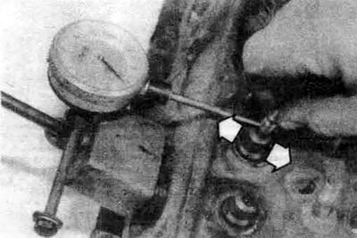
10.14. To determine the clearance of the valve stem with the guide, you can use a micrometer (move the valve stem as shown in the photo)
Valves
15. Carefully inspect each valve for uneven wear, warping, cracks, pitting, and burnout. Rotate the valve to make sure it is not bent (see illustration). Check for pitting and excessive wear on the stem ends. If any of these signs are present, the valves need to be repaired in a workshop.
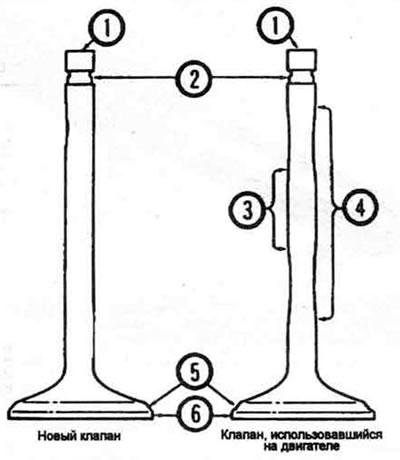
10.15. Check the degree of wear of the valves at the points shown. 1. Valve end, 2. Cracker groove, 3. Rod (least worn area), 4. Rod (most worn area), 5. Working surface of valve chamfer, 6. Edge
16. Measure the edge width of each valve (see illustration). Any valves that have a edge width less than the specification must be replaced with new ones.
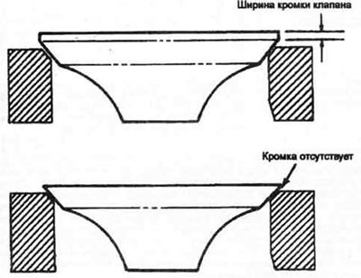
10.16. The width of the edge of each valve must correspond to specifications (if the edge is missing, the valve cannot be used again)
Valve train elements
17. Check the valve springs for wear (at the ends) and for pitting. Measure the free length of the spring and compare with the specification (see illustration). All springs shorter than the specification must be replaced with new ones. To decide whether old springs can be used when assembling the engine, the force of all springs must be checked (this can be done in a specialized workshop).
18. Place each spring on a flat surface and check its flatness (see illustration). If some springs are warped or weakened, replace them with new ones.
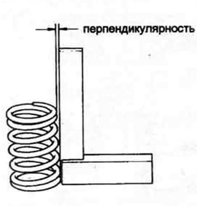
10.18. Check the flatness of each spring
19. Check for wear and damage to the valve spring plates and crackers. All suspicious parts should be replaced with new ones, as their failure during engine operation can lead to serious engine damage.
Valve rocker arm components
20. The procedures for checking the valve rocker arms and their axles are described in part A Chapter 2.
Injector valves
21. Make sure that all injection valves move freely in the housing without any play. Do not move parts from one injection valve to another. If any parts are worn, replace the valve assembly.
22. Check the valve head and seat for damage or signs of sticking. Check the integrity of the spring.
23. All damaged and worn parts should be replaced with new ones.
24. If during inspection it is found that the valve components are in poor condition and worn beyond the norm, which is usually the case on an engine subject to overhaul, assemble the valves into the cylinder head and use the recommendations section 10. concerning valve maintenance.