



Contents: Preliminary operations ⤓ Removal the camshaft toothed pulley ⤓ Removal the power steering oil pump ⤓ Removal the cylinder head mounting…⤓
Preliminary operations
1. Disconnect and remove the battery.
2. Drain the coolant and engine oil.
3. Disconnect and remove the air filter elements.
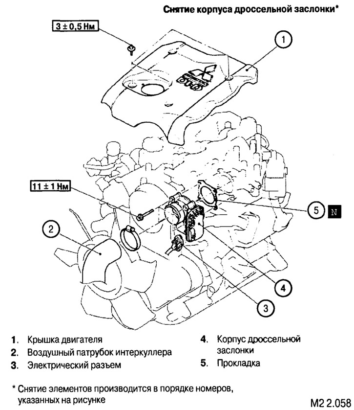
4. Remove the throttle body (see Fig. M2 2.058).
5. Disconnect and remove the EGR system components (see Fig. M2 2.059).
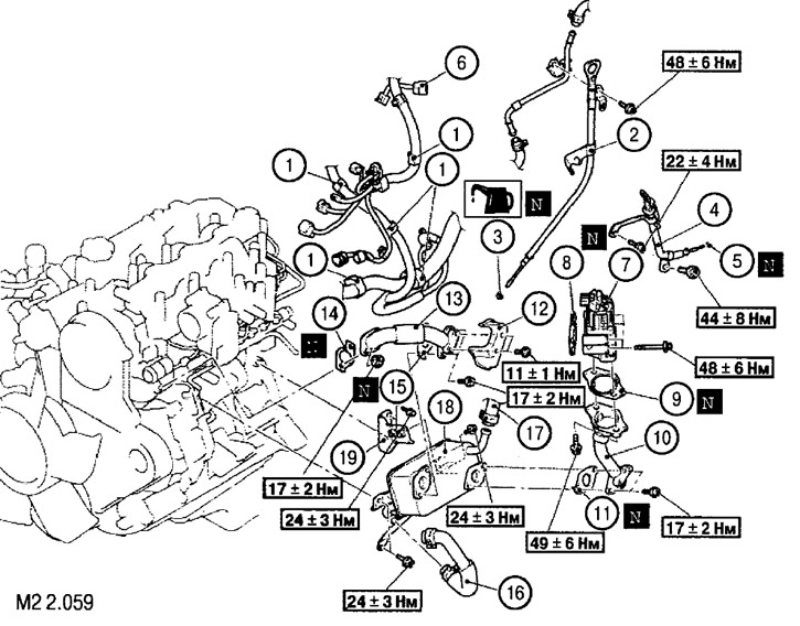
Removal EGR system components: 1. Harness holder latch; 2. Oil dipstick with tube assembly; 3. Sealing ring; 4. Transmission oil dipstick with tube assembly; 5. Sealing ring; 6. EGR valve connector; 7. EGR valve; 8. EGR valve gasket; 9. Pipe gasket; 10. EGR valve pipe "B"; 11. Pipe gasket; 12. Thermal protection screen; 13. EGR valve pipe "A"; 14. Pipe gasket; 15. Pipe gasket; 16. Cooling system rods; 17. Heater hose; 18. EGR system exhaust gas cooler; 19. Cooler mounting bracket
* The elements are removed in the order of the numbers shown in the figure
6. Disconnect and remove the intake manifold elements (see Fig. M2 2.060).
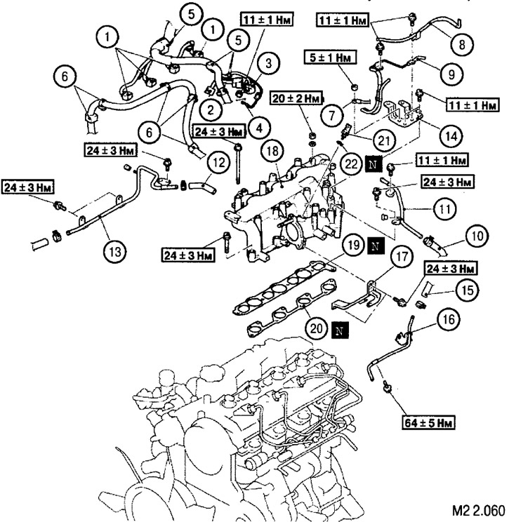
Removal the intake manifold components: 1. Electrical connectors of injectors; 2. Electrical connector of the inlet air temperature sensor; 3. Fuel pressure sensor electrical connector; 4. Glow plug wire; 5. Harness holder latch; 6. Battery cable holder latch; 7. Battery cable terminal "ground"; 8. Vacuum hose and tube assembly; 9. Vacuum hose and tube assembly; 10. Brake booster hose; 11. Vacuum tube "B"; 12. Vacuum hose; 13. Vacuum tube "A"; 14. Engine cover bracket; 15. Fuel hose "D"; 16. Fuel line; 17. Intake manifold bracket; 18. Intake manifold assembly; 19. Intake manifold gasket; 20. Intake manifold gasket; 21. Inlet air temperature sensor; 22. Gasket
* The elements are removed in the order of the numbers shown in the figure
7. Disconnect and remove the valve cover and fuel injector housings (described above).
8. Remove the fan impeller assembly with the clutch, covers and timing belts (described above).
9. Disconnect and remove the fuel injection system components (see Fig. M2 2.061).
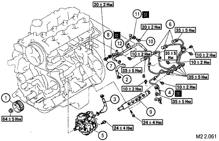
Removal the fuel supply and injection system components: 1. Fuel injection pump pulley; 2. Fuel return line hose; 3. Fuel supply line hose; 4. High pressure pipe (TNVD-TKVD); 5. Fuel injection pump assembly; 6. High pressure pipes (HP injectors); 7. Banjo bolt; 8. Gasket; 9. Fuel manifold (FMHP) assembly; 10. Banjo bolt; 11. Gasket; 12. Fuel return pipe
* The elements are removed in the order of the numbers shown in the figure
10. Disconnect and remove the turbocharger and exhaust manifold (see Fig. M2 2.062).
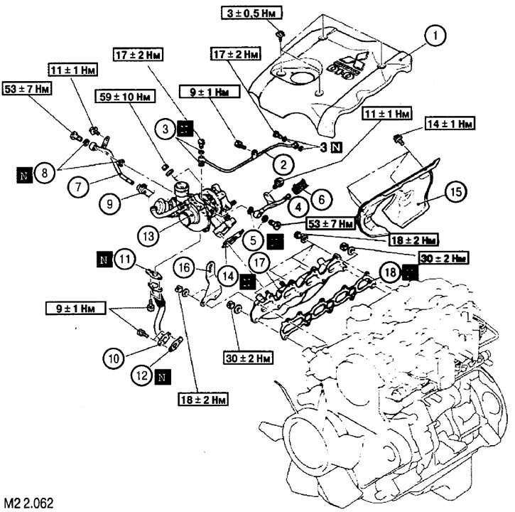
Removal the turbocharger and exhaust manifold: 1. Lubrication system tube; 2. Gasket; 3. Cooling system pipe "B"; 4. Gasket; 5. Cooling system hose; 6. Cooling system pipe "C"; 7. Gasket; 8. Cooling system hose; 9. Oil return pipe to the lubrication system; 10. Pipe gasket; 11. Pipe gasket; 12. Turbocharger assembly; 13. Turbocharger gasket; 14. Thermal protection screen; 15. Bracket; 16. Exhaust manifold; 17. Collector gasket
* The elements are removed in the order of the numbers shown in the figure
11. After completing all preliminary work, remove the cylinder head (see Fig. M2 2.063).
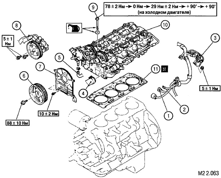
Removal the cylinder head: 1. Connector of the emergency temperature sensor 0Ж; 2. Coolant temperature gauge connector; 3. Glow plug connection terminal; 4. Upper radiator hose; 5. Oil line pipe; 6. Timing pulley of the camshaft drive; 7. Rear timing belt cover; 8. Power steering pump assembly; 9. Cylinder head mounting screws; 10. Cylinder head assembly; 11. Cylinder head gasket
* The elements are removed in the order of the numbers shown in the figure
Removal the camshaft toothed pulley
1. Holding the camshaft using tools (1) and (2), unscrew the mounting nut and remove the gear.
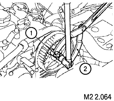
Note: When installing the pulley, hold it with the tools and tighten the fastening screw to a torque of 88±10 Nm.
Removal the power steering oil pump
Note: the power steering pump (8) (see Fig. M2 2.063) is removed as an assembly without disconnecting the corresponding lines.
Removal the cylinder head mounting screws
The head mounting screws are unscrewed in pairs (loosening in two or three steps), in accordance with the numbering shown in the figure (see Fig. M2 2.065).
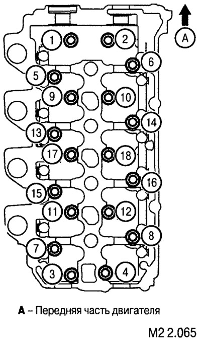
Note: Before removing the screws, use a punch to mark the head of each screw. Make one mark each time you remove the screws and the cylinder head.
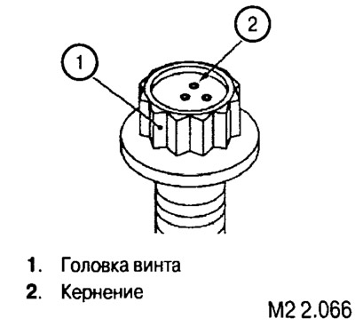
When the number of marks reaches five, the screw must be replaced with a new one, even if its length corresponds to the nominal value.
The nominal length of the cylinder head mounting screws is no more than 93 mm.