



Contents: Checking the head and valve group…⤓ Checking the flatness of the…⤓ Removal the crackers securing the…⤓ Installing valve stem seals (valve…⤓ Valve stem cap ⤓ Valve ⤓
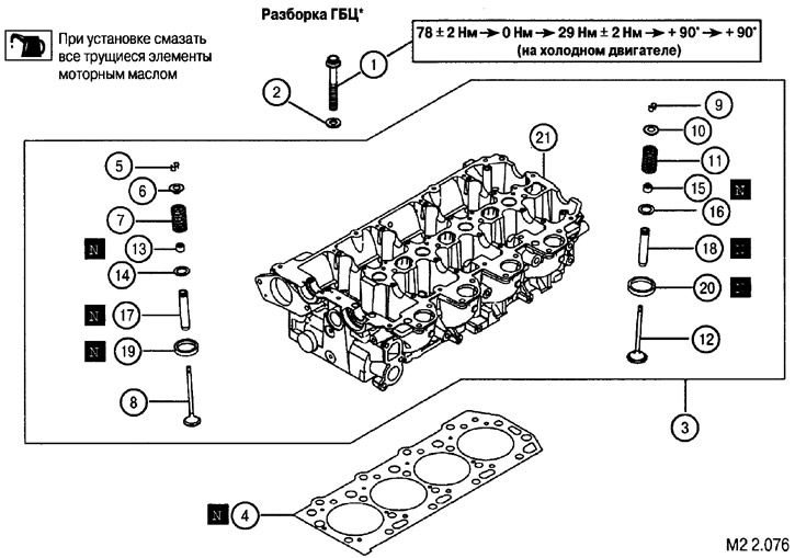
Elements of the cylinder head valve mechanism: 1. Cylinder head mounting screws; 2. Washer; 3. Cylinder head assembly; 4. Cylinder head gasket; 5. Valve crackers; 6. Valve spring plate; 7. Valve spring; 8. Inlet valve; 9. Valve crackers; 10. Valve spring plate; 11. Valve spring; 12. Exhaust valve; 13. Oil seal; 14. Valve spring seat; 15. Oil seal; 16. Valve spring seat; 17. Inlet valve guide bushing; 18. Exhaust valve guide bushing; 19. Valve spring seat; 20. Valve spring seat; 21. Cylinder head
Checking the head and valve group elements
After disassembling the cylinder head, remove any gasket residue, oil, scale, etc. from its surfaces. After cleaning, blow out all channels with compressed air.
Inspect the condition of the mating surfaces, camshaft bearing beds, and intake and exhaust valve seats.
Checking the flatness of the cylinder head
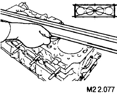
Using a measuring ruler and feeler gauges, check the plane of the mating surface (for installing the gasket) in the directions shown in the figure.
(The article was obtained from this portal: MitsubishiMan)
Standard value: 0.05 mm.
Maximum allowable value: 0.2 mm.
Removal the crackers securing the upper valve spring support
Caution: When removing crackers, set the piston of each cylinder to the TDC position.
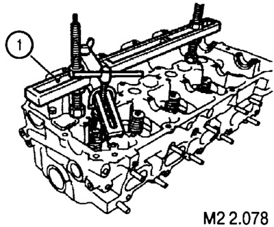
1. To compress the valve spring in order to remove the valve crackers, install the device (1) on the cylinder head.
2. Compress the valve spring, remove the crackers, plate and valve spring.
3. Remove the oil seal from the valve guide.
Installing valve stem seals (valve seals)
Note: The use of used seals is not permitted.
1. Apply a small amount of engine oil to the inner working lip of the oil seal and press it onto the guide using the drift (4).

2. After installing new seals, install the valve spring and plate, compress the spring with the tool (1) (see Fig. M2 2.078) and install the crackers on the valve stem.
Valve stem cap
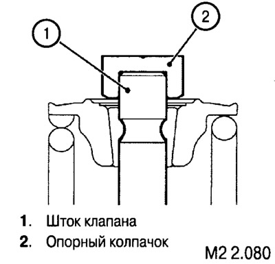
The cap on the valve stem must be installed tightly.
Valve
Checking the contact surface width and valve plate thickness
1. The width of the contact surface must be uniform and located in the center of the working chamfer of the valve.
Standard value: 1.1-1.5 mm.
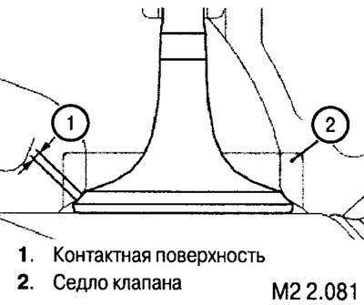
In case of incorrect contact, it is necessary to grind or replace the valve, replace or restore the geometric characteristics of the valve seat.
2. Measure the thickness of the valve plate.
Default value:
- inlet valve: 1.3 mm;
- outlet valve: 1.5 mm.
Maximum permissible value:
- inlet valve: 0.8 mm;
- outlet valve: 1.0 mm.
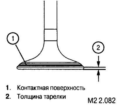
If the thickness is less than the maximum allowable value, replace the valve.
Checking the valve length
Default value:
- inlet valve: 107.58 mm;
- exhaust valve: 107.98 mm.
Maximum permissible value:
- inlet valve: 107.08 mm;
- exhaust valve: 107.48 mm.
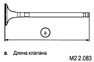
If the length is less than the maximum allowable value, replace the valve.
Valve spring
Measure the height of the spring and its deviation from the vertical axis (in a free state).
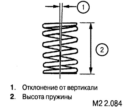
Spring length:
- standard value: 54.3 mm;
- maximum permissible value: 53.3 mm.
Deviation from vertical:
- standard value: no more than 2°;
- maximum permissible value: 4°.
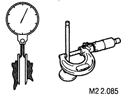
If the obtained values exceed the maximum permissible values, the valve or guide bushing may need to be replaced.