



2. To make checking easier, remove all spark plugs.
3. Remove the cylinder head cover.
4. Turn the crankshaft clockwise until the mark on the pulley aligns with the "T" mark on the scale on the lower timing belt cover.
5. Move the rocker arms of the 1st and 4th cylinders up and down by hand to determine in which cylinder the piston is at TDC in the compression stroke. If there are gaps between the rocker arms of the valves and the intake and exhaust valves of one of the cylinders, the piston of this cylinder is at TDC in the compression stroke.
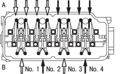
Fig. 3.4. When installing the piston of the 1st cylinder at TDC, measure the clearance of the valves indicated by white arrows, and after installing the piston of the 4th cylinder at TDC, measure the clearance of the valves indicated by black arrows: A - intake valve side; B – exhaust valve side
6. If the piston of the 1st cylinder is at TDC of the compression stroke, it is necessary to check and adjust the clearances in the valve drive, shown by the white arrow in Fig. 3.4; if the piston of the 4th cylinder is at TDC of the compression stroke, the adjustment is carried out on the rocker arms shown by the black arrow in Fig. 3.4.
7. Measure the valve clearance.
8. If the clearance is not within the specified value, loosen the rocker arm adjusting bolt lock nut and adjust the clearance by measuring it with a feeler gauge and turning the adjusting bolt.
9. Nominal clearance in the valve drive (on a hot engine):
- inlet valve 0.20 mm;
- outlet valve 0.30 mm.
10. While holding the adjusting bolt with a screwdriver (to prevent it from turning), tighten the lock nut to a torque of 9 N·m.
11. Turn the crankshaft 360° until the mark on the pulley coincides with the "T" mark on the scale of the lower timing belt cover.
12. Adjust the clearances in the drive of the remaining valves as indicated earlier.
13. Install the cylinder head cover.
14. Screw in the spark plugs and tighten them to a torque of 25 Nm.
(The material was borrowed from the website: MITSUBISHIMAN.ru)