



Share with friends:
Fuel injection system GDI Mitsubishi Space Star

Technical data
Throttle assembly diameter of the inner hole of the throttle assembly, mm — 60 throttle position sensor - variable resistance throttle control servo motor - stepper...
Throttle assembly diameter of the inner hole of the throttle assembly, mm — 60 throttle position sensor - variable resistance throttle control servo motor - stepper...
Self-diagnosis function
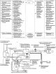
Fig. 6.1. Functional diagram of the direct fuel injection system into the engine cylinders (GDI) of a car manufactured since 1999 If a malfunction occurs in any of the...
Fig. 6.1. Functional diagram of the direct fuel injection system into the engine cylinders (GDI) of a car manufactured since 1999 If a malfunction occurs in any of the...
Checking using the «DATA LIST» modes
1. Perform a check using the "DATA LIST" and "ACTUATOR TEST" modes of the MUT-II. If a fault is detected, check the vehicle's electrical wiring, related components and...
1. Perform a check using the "DATA LIST" and "ACTUATOR TEST" modes of the MUT-II. If a fault is detected, check the vehicle's electrical wiring, related components and...
Diagnostic trouble codes for cars produced since 1999
Code Malfunction 11 Oxygen concentration sensor and its electrical circuit 12 Air flow meter and its electrical circuit 13 Engine air temperature sensor and its...
Code Malfunction 11 Oxygen concentration sensor and its electrical circuit 12 Air flow meter and its electrical circuit 13 Engine air temperature sensor and its...
Diagnostic trouble codes for cars produced since 2000
Code Malfunction — Electronic engine control unit (cars with manual transmission) or electronic engine and gearbox control unit (cars with automatic transmission) P0100...
Code Malfunction — Electronic engine control unit (cars with manual transmission) or electronic engine and gearbox control unit (cars with automatic transmission) P0100...
Diagnostics in the «DIAGNOSIS 2» mode on a car manufactured since 2000
1. Using the MUT-II device, switch the electronic control unit to the diagnostic mode "DIAGNOSIS 2". 2. Conduct a road test. 3. Read diagnostic codes and correct any...
1. Using the MUT-II device, switch the electronic control unit to the diagnostic mode "DIAGNOSIS 2". 2. Conduct a road test. 3. Read diagnostic codes and correct any...
Checking using the «DATA LIST» and «ACTUATOR TEST» modes of MUT-II on a car manufactured since 2000
1. Perform the test using the MUT-II DATA LIST and ACTUATOR TEST modes. If a fault is detected, check the vehicle's electrical wiring, relevant components and parts. 2....
1. Perform the test using the MUT-II DATA LIST and ACTUATOR TEST modes. If a fault is detected, check the vehicle's electrical wiring, relevant components and parts. 2....
Freeze Frame data on a vehicle manufactured since 2000
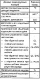
When the engine control module (vehicles with manual transmission) or the engine and automatic transmission control module (vehicles with automatic transmission) detects...
When the engine control module (vehicles with manual transmission) or the engine and automatic transmission control module (vehicles with automatic transmission) detects...
Cleaning the throttle assembly
1. Start the engine and warm it up to a temperature of 80°C, then turn it off. 2. Disconnect the air intake hose from the throttle assembly. 3. Spray aerosol cleaning...
1. Start the engine and warm it up to a temperature of 80°C, then turn it off. 2. Disconnect the air intake hose from the throttle assembly. 3. Spray aerosol cleaning...

Adjusting the throttle position sensor
Fig. 6.3. Position of the engine crankshaft speed adjustment screw at idle (fixed SAS) 1. Connect the MUT-II device to the diagnostic connector. 2. Disconnect the...
Fig. 6.3. Position of the engine crankshaft speed adjustment screw at idle (fixed SAS) 1. Connect the MUT-II device to the diagnostic connector. 2. Disconnect the...

Adjusting the accelerator pedal position sensor on a car manufactured since 1999
Warnings 1. Do not move the accelerator pedal position sensor unless absolutely necessary, as its position is adjusted with high precision at the factory (Fig. 6.6). 2....
Warnings 1. Do not move the accelerator pedal position sensor unless absolutely necessary, as its position is adjusted with high precision at the factory (Fig. 6.6). 2....

Adjusting the accelerator pedal position sensor on a car manufactured since 2000
Warnings 1. Do not move the accelerator pedal position sensor unless absolutely necessary, as its position is adjusted with high precision at the factory (Fig. 6.9). 2....
Warnings 1. Do not move the accelerator pedal position sensor unless absolutely necessary, as its position is adjusted with high precision at the factory (Fig. 6.9). 2....

Checking the pressure generated by the fuel pump
1. Reduce the pressure in the fuel system. Warning: Before disconnecting the fuel lines, relieve the pressure in the fuel system, otherwise pressurized fuel will leak...
1. Reduce the pressure in the fuel system. Warning: Before disconnecting the fuel lines, relieve the pressure in the fuel system, otherwise pressurized fuel will leak...

Measuring fuel pressure on the line between the high-pressure fuel pump and the injectors
Note: Measuring the pressure on the line between the high-pressure fuel pump and the injectors should be carried out after you have made sure that the fuel pressure...
Note: Measuring the pressure on the line between the high-pressure fuel pump and the injectors should be carried out after you have made sure that the fuel pressure...
Checking the fuel system for leaks
1. Connect the MUT-II device to the diagnostic connector. 2. Disconnect the intermediate connector of the injectors (see Fig. 6.15, 6.16). 3. Turn the ignition switch...
1. Connect the MUT-II device to the diagnostic connector. 2. Disconnect the intermediate connector of the injectors (see Fig. 6.15, 6.16). 3. Turn the ignition switch...

Reducing pressure in the fuel system
Before disconnecting the fuel lines, relieve the pressure in the fuel system, otherwise pressurized fuel will leak out of the fuel system. 1. Remove the rear seat. 2....
Before disconnecting the fuel lines, relieve the pressure in the fuel system, otherwise pressurized fuel will leak out of the fuel system. 1. Remove the rear seat. 2....
Checking the operation of the fuel pump
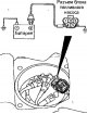
Fig. 6.19. Location of fuel system elements in a vehicle: A-accelerator pedal position sensor; B - relay for generating signals for injector control; C - ignition coil;...
Fig. 6.19. Location of fuel system elements in a vehicle: A-accelerator pedal position sensor; B - relay for generating signals for injector control; C - ignition coil;...

Checking the fuel pump pressure control relay and throttle actuator
To check, connect an ohmmeter to contacts 1 and 3 of the relay, and it should show an open circuit. Then, with one additional wire, connect contact 2 of the relay...
To check, connect an ohmmeter to contacts 1 and 3 of the relay, and it should show an open circuit. Then, with one additional wire, connect contact 2 of the relay...

Checking the relay of the injector control signal generator
To check, connect an ohmmeter to contacts 1 and 2 of the relay, and it should show an open circuit. Then, with one additional wire, connect contact 4 of the relay...
To check, connect an ohmmeter to contacts 1 and 2 of the relay, and it should show an open circuit. Then, with one additional wire, connect contact 4 of the relay...

Checking the engine air temperature sensor
1. Disconnect the connector from the air flow meter (Fig. 6.23). Fig. 6.23. Air flow meter location 2. Measure the resistance between pins 5 and 6 of the connector....
1. Disconnect the connector from the air flow meter (Fig. 6.23). Fig. 6.23. Air flow meter location 2. Measure the resistance between pins 5 and 6 of the connector....

Checking the coolant temperature sensor
Warning: When removing and installing the coolant temperature sensor, do not touch its connector (plastic part) with a tool. 1. Drain the coolant, disconnect the...
Warning: When removing and installing the coolant temperature sensor, do not touch its connector (plastic part) with a tool. 1. Drain the coolant, disconnect the...
Checking the throttle position sensor
1. Disconnect the connector from the throttle position sensor ( see fig. 6.4 ). 2. Measure the resistance between contacts 1 and 3 of the sensor connector (see Fig. 6.4...
1. Disconnect the connector from the throttle position sensor ( see fig. 6.4 ). 2. Measure the resistance between contacts 1 and 3 of the sensor connector (see Fig. 6.4...
Checking the accelerator pedal position sensor
1. Disconnect the connector from the accelerator pedal position sensor ( see fig. 6.6 ). 2. Measure the resistance between pins 2 and 1, as well as 8 and 7 of the sensor...
1. Disconnect the connector from the accelerator pedal position sensor ( see fig. 6.6 ). 2. Measure the resistance between pins 2 and 1, as well as 8 and 7 of the sensor...
Checking the accelerator pedal switch
1. Disconnect the connector from the accelerator pedal position sensor (see Fig. 6.6). 2. Measure the resistance between contacts 4 and 5 of the accelerator pedal...
1. Disconnect the connector from the accelerator pedal position sensor (see Fig. 6.6). 2. Measure the resistance between contacts 4 and 5 of the accelerator pedal...

Checking the oxygen concentration sensor
The heated oxygen sensor detects the oxygen concentration in the exhaust gases and converts it into a voltage, which it transmits to the engine control unit (ECU). The...
The heated oxygen sensor detects the oxygen concentration in the exhaust gases and converts it into a voltage, which it transmits to the engine control unit (ECU). The...
Checking fuel injectors
1. Disconnect the fuel injector intermediate connector ( see fig. 6.15 ). 2. Measure the resistance between the contacts of the intermediate connector of the fuel...
1. Disconnect the fuel injector intermediate connector ( see fig. 6.15 ). 2. Measure the resistance between the contacts of the intermediate connector of the fuel...

Checking the throttle servo
Functional check 1. Disconnect the air pipe from the throttle assembly. 2. Turn on the ignition. 3. Make sure that the throttle valve opens according to the amount of...
Functional check 1. Disconnect the air pipe from the throttle assembly. 2. Turn on the ignition. 3. Make sure that the throttle valve opens according to the amount of...

Checking the Clutch Pedal Position Switch
1. Disconnect the connector from the clutch pedal position switch. 2. Measure the resistance between contacts 1 and 2 of the switch connector (Fig. 6.32). Fig. 6.32....
1. Disconnect the connector from the clutch pedal position switch. 2. Measure the resistance between contacts 1 and 2 of the switch connector (Fig. 6.32). Fig. 6.32....

High pressure fuel pump for engines manufactured since 1999
Removal Reduce the pressure in the fuel system. Warning: Before disconnecting the fuel lines, relieve the pressure in the fuel system, otherwise pressurized fuel will...
Removal Reduce the pressure in the fuel system. Warning: Before disconnecting the fuel lines, relieve the pressure in the fuel system, otherwise pressurized fuel will...

High pressure fuel pump for engines manufactured since 2000
Removal Reduce the pressure in the fuel system. Warning: Before disconnecting the fuel lines, relieve the pressure in the fuel system, otherwise pressurized fuel will...
Removal Reduce the pressure in the fuel system. Warning: Before disconnecting the fuel lines, relieve the pressure in the fuel system, otherwise pressurized fuel will...

Fuel injectors for engines manufactured since 1999
Removal Reduce the pressure in the fuel system. Remove the bolts and remove the engine cover. Remove the air filter. Remove the intake manifold. Unscrew the bolts and...
Removal Reduce the pressure in the fuel system. Remove the bolts and remove the engine cover. Remove the air filter. Remove the intake manifold. Unscrew the bolts and...

Fuel injectors for engines produced since 2000
Removal Reduce the pressure in the fuel system. Remove the bolts and remove the engine cover. Disconnect the connector from the fuel pressure sensor (Fig. 6.49). Fig....
Removal Reduce the pressure in the fuel system. Remove the bolts and remove the engine cover. Disconnect the connector from the fuel pressure sensor (Fig. 6.49). Fig....

Throttle body of the engine since 1999
Removal Drain the coolant from the cooling system. Remove the air filter housing. Remove the bolts and remove the engine cover. Remove the air intake hose. Disconnect...
Removal Drain the coolant from the cooling system. Remove the air filter housing. Remove the bolts and remove the engine cover. Remove the air intake hose. Disconnect...

Disassembly and assembly of the throttle unit of the engine since 1999
Disassembly Remove the throttle assembly. Remove the screws and throttle position sensor (Fig. 6.53). Fig. 6.53. Throttle assembly of the engine since 1999: 1 - throttle...
Disassembly Remove the throttle assembly. Remove the screws and throttle position sensor (Fig. 6.53). Fig. 6.53. Throttle assembly of the engine since 1999: 1 - throttle...

Throttle body of the engine since 2000
Removal Drain the coolant from the cooling system. Remove the bolts and remove the engine cover. Remove the air intake hose. Disconnect the connectors from the throttle...
Removal Drain the coolant from the cooling system. Remove the bolts and remove the engine cover. Remove the air intake hose. Disconnect the connectors from the throttle...
Disassembly and assembly of the throttle unit of the engine since 2000
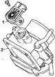
Disassembly Remove the throttle assembly. Remove the screws and throttle position sensor (Fig. 6.58). Fig. 6.58. Throttle assembly of the engine since 2000: 1 - throttle...
Disassembly Remove the throttle assembly. Remove the screws and throttle position sensor (Fig. 6.58). Fig. 6.58. Throttle assembly of the engine since 2000: 1 - throttle...

Injector control pulse generator
Removal Disconnect the cable from the negative battery terminal. Press the injector control pulse generator connector lock in the location shown in Figure 6.61 and...
Removal Disconnect the cable from the negative battery terminal. Press the injector control pulse generator connector lock in the location shown in Figure 6.61 and...

Fuel tank
The fuel tank is located under the vehicle's underbody, beneath the rear seats, increasing safety and luggage space. To prevent fuel leakage in the event of a vehicle...
The fuel tank is located under the vehicle's underbody, beneath the rear seats, increasing safety and luggage space. To prevent fuel leakage in the event of a vehicle...
Technical data of the GDI fuel injection system
Electronic control unit - E2T71279 Basic data for adjustments and control Resistance of the temperature sensor of the air entering the engine, kOhm at a temperature of...
Electronic control unit - E2T71279 Basic data for adjustments and control Resistance of the temperature sensor of the air entering the engine, kOhm at a temperature of...

Self-diagnosis function. Multi-point fuel injection (MPI) system
If a malfunction occurs in any of the following components of the multipoint injection (MPI) system, the engine malfunction indicator lamp comes on ("CHECK ENGINE")...
If a malfunction occurs in any of the following components of the multipoint injection (MPI) system, the engine malfunction indicator lamp comes on ("CHECK ENGINE")...
This section is available on: russian, bulgarian, belarusian, ukrainian, serbian, croatian, romanian, polish, slovak, hungarian
Similar materials for other Mitsubishi models
➤ Power unit: Fuel injection GDI Mitsubishi Colt 4 and 5 (1991-2003)
➤ Power unit: GDI fuel injection system Mitsubishi Lancer 9 (2000-2007, petrol)
Link in different formats to this section
TEXTHTMLBB Code
- General information
- User manual
- Maintenance
- Power unit
- Petrol engines 4G9
- Diesel engines FBQT
- Diesel engines F9Q
- Cooling system
- Injection system (MPI)
- Injection system (GDI)
- Engine electrical equipment
- Transmission
- Clutch
- Mechanical gearbox
- Automatic gearbox
- Chassis and running gear
- Steering
- Brake system
- Front suspension and shafts
- Rear suspension
- Body and interior
- Exterior (external elements)
- Interior (internal elements)
- Doors, locks and windows
- Air conditioner
- Electrical equipment
- Equipment and devices
- Headlights and lighting
- Electrical circuits
- General information
- User manual
- Maintenance
- Power unit
- Petrol engines 4G9
- Petrol engines 4G1
- Diesel engines F9Q1
- Cooling system
- Fuel injection system GDI
- Fuel injection system MPI
- Diesel supply system F9Q1
- Ignition system
- Diesel preheating
- Transmission
- Clutch
- Mechanical gearbox
- Automatic gearbox
- Chassis and running gear
- Suspension and drive shafts
- Brake system
- Steering
- Body and interior
- Exterior (external elements)
- Interior (internal elements)
- Doors, locks and windows
- Heating and air conditioning
- Electrical equipment
- Power devices
- Equipment and devices