



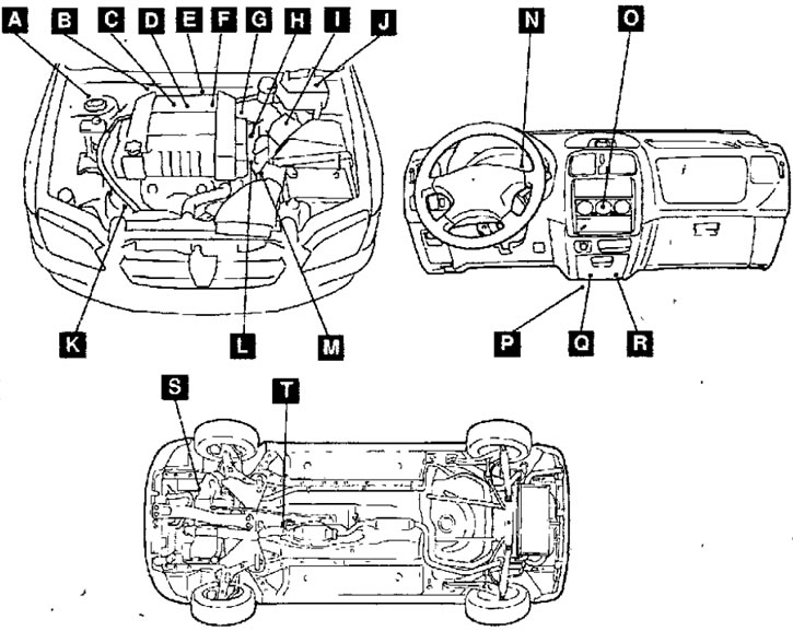
Fig. 6.19. Location of fuel system elements in a vehicle:A-accelerator pedal position sensor; B - relay for generating signals for injector control; C - ignition coil; D - injectors; E - knock sensor; F - EGR valve; G - throttle position sensor, throttle servo, purge solenoid valve of the adsorber; H - vehicle speed sensor; I - air flow meter (together with intake manifold air temperature and atmospheric pressure sensors); J - air conditioner relay; K — hydraulic power steering fluid pressure sensor; L - fuel pressure sensor, camshaft position sensor, coolant temperature sensor; N - Engine malfunction indicator lamp (CHECK ENGINE); R - diagnostic connector; Q- Throttle Controller, Throttle Servo Relay, Engine Control Unit; R - fuel pump relay, engine control relay; S - transmission oil temperature sensor (manual transmission); T- oxygen concentration sensor; M - crankshaft position sensor; O - air conditioner switch
1. Check the operation of the low-pressure fuel pump by forcibly turning it on using the MUT-II device.
2. If the fuel pump does not work, check it as follows, and if the pump does not work, check its power supply circuits.
(1) Turn the ignition switch key to the OFF position.
(2) Remove the rear seat.
(3) Remove the protective cover.
(4) Disconnect the connector from the fuel pump unit. Connect contact 4 on the relay connector side to the battery, and connect contact 5 of the connector to ground (Fig. 6.18). Make sure that the noise of the pump operating can be heard. Since the fuel pump is installed in the fuel tank, in order to improve the audibility of the sound of the pump operating, unscrew the filler cap of the fuel tank.
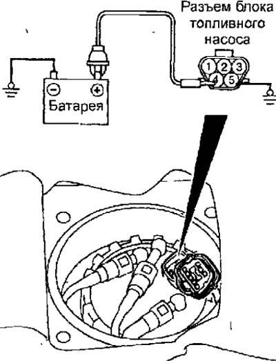
Fig. 6.18. Checking the fuel pump operation
(5) Pinch the fuel supply hose to determine if the fuel pump is generating pressure.
(6) Connect the connector to the fuel pump unit.
(7) Install the rear seat and protective cover.