



Share with friends:
Vehicle Injection (GDI) Mitsubishi Carisma


General information about the direct fuel injection (GDI) system
Some vehicles are equipped with a system with electronic throttle opening control. The electronic engine control unit uses the accelerator pedal position sensor (APS) to...
Some vehicles are equipped with a system with electronic throttle opening control. The electronic engine control unit uses the accelerator pedal position sensor (APS) to...

Engine malfunction indicator lamp («CHECK ENGINE»)
When replacing the electronic engine control unit, the electronic immobilizer control unit and ignition keys must also be replaced. The engine malfunction indicator lamp...
When replacing the electronic engine control unit, the electronic immobilizer control unit and ignition keys must also be replaced. The engine malfunction indicator lamp...
Relieving pressure in the fuel system
When removing fuel pipes, hoses, etc., it is necessary to take into account that the fuel pressure in the line is usually quite high. Therefore, in order to avoid fuel...
When removing fuel pipes, hoses, etc., it is necessary to take into account that the fuel pressure in the line is usually quite high. Therefore, in order to avoid fuel...

Checking the operation of the low pressure fuel pump
Check the operation of the low-pressure fuel pump using the MUT–II device by forcibly turning on the pump. If the low pressure fuel pump is OK, check its electrical...
Check the operation of the low-pressure fuel pump using the MUT–II device by forcibly turning on the pump. If the low pressure fuel pump is OK, check its electrical...
Cleaning the throttle body
1. Start the engine, warm it up until the coolant temperature is 80°C or higher, and then turn it off. 2. Disconnect the inlet hose from the throttle body. 3. Spray the...
1. Start the engine, warm it up until the coolant temperature is 80°C or higher, and then turn it off. 2. Disconnect the inlet hose from the throttle body. 3. Spray the...

Measuring low fuel pressure between low and high pressure fuel pumps
1. To prevent fuel splashing, relieve residual pressure from the high pressure fuel line. 2. Disconnect the high pressure fuel hose from the high pressure fuel pump....
1. To prevent fuel splashing, relieve residual pressure from the high pressure fuel line. 2. Disconnect the high pressure fuel hose from the high pressure fuel pump....

Measuring fuel pressure on the line between the high-pressure fuel pump and the injectors
Caution! The pressure in the line between the high-pressure fuel pump and the injectors must be measured after you have made sure that the fuel pressure between the...
Caution! The pressure in the line between the high-pressure fuel pump and the injectors must be measured after you have made sure that the fuel pressure between the...

Checking the tightness of the power supply system
1. Connect the MUT-II device to the diagnostic connector. Fig. 8.4. Location of the intermediate connector (1) of the injectors 2. Disconnect the intermediate connector...
1. Connect the MUT-II device to the diagnostic connector. Fig. 8.4. Location of the intermediate connector (1) of the injectors 2. Disconnect the intermediate connector...

Adjusting the throttle position sensor
1. Connect the MUT-II device to the diagnostic connector. Fig. 8.5. Location of the throttle position sensor (1) and view of the connector from the sensor side (2) 2....
1. Connect the MUT-II device to the diagnostic connector. Fig. 8.5. Location of the throttle position sensor (1) and view of the connector from the sensor side (2) 2....
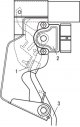
Adjusting the accelerator pedal position sensor
Caution! Do not attempt to change the position of the accelerator pedal position sensor. This sensor is installed at the factory with high precision and does not require...
Caution! Do not attempt to change the position of the accelerator pedal position sensor. This sensor is installed at the factory with high precision and does not require...

High pressure fuel pump — removal and installation
Removal To remove, follow these steps in sequence. 1. Remove the engine protective cover. 2. Relieve fuel pressure (prevent fuel splashing). 3. Remove the air filter. 4....
Removal To remove, follow these steps in sequence. 1. Remove the engine protective cover. 2. Relieve fuel pressure (prevent fuel splashing). 3. Remove the air filter. 4....

Injectors — removal and installation
Removal To remove, follow these steps in sequence. 1. Disconnect the cable from the negative terminal of the battery. 2. Remove the engine protective cover. 3. Relieve...
Removal To remove, follow these steps in sequence. 1. Disconnect the cable from the negative terminal of the battery. 2. Remove the engine protective cover. 3. Relieve...

Throttle body — removal and installation
Cars produced since 1999 Removal Disconnect the cable from the negative battery terminal. To remove, follow these steps in sequence. 1. Drain the coolant from the engine...
Cars produced since 1999 Removal Disconnect the cable from the negative battery terminal. To remove, follow these steps in sequence. 1. Drain the coolant from the engine...
This section is available on: russian, bulgarian, belarusian, ukrainian, serbian, croatian, romanian, polish, slovak, hungarian
Similar materials for other Mitsubishi models
➤ Power unit: Fuel injection GDI Mitsubishi Colt 4 and 5 (1991-2003)
➤ Power unit: GDI fuel injection system Mitsubishi Lancer 9 (2000-2007, petrol)
Link in different formats to this section
TEXTHTMLBB Code
- General information
- User manual
- Maintenance
- Power unit
- Petrol engines 4G9
- Diesel engines FBQT
- Diesel engines F9Q
- Cooling system
- Injection system (MPI)
- Injection system (GDI)
- Engine electrical equipment
- Transmission
- Clutch
- Mechanical gearbox
- Automatic gearbox
- Chassis and running gear
- Steering
- Brake system
- Front suspension and shafts
- Rear suspension
- Body and interior
- Exterior (external elements)
- Interior (internal elements)
- Doors, locks and windows
- Air conditioner
- Electrical equipment
- Equipment and devices
- Headlights and lighting
- Electrical circuits
- General information
- User manual
- Maintenance
- Power unit
- Petrol engines 4G9
- Petrol engines 4G1
- Diesel engines F9Q1
- Cooling system
- Fuel injection system GDI
- Fuel injection system MPI
- Diesel supply system F9Q1
- Ignition system
- Diesel preheating
- Transmission
- Clutch
- Mechanical gearbox
- Automatic gearbox
- Chassis and running gear
- Suspension and drive shafts
- Brake system
- Steering
- Body and interior
- Exterior (external elements)
- Interior (internal elements)
- Doors, locks and windows
- Heating and air conditioning
- Electrical equipment
- Power devices
- Equipment and devices