



Share with friends:
Diesel engines F9Q1 car Mitsubishi Space Star

Technical data
General information Type - F9Q1 Working volume, cm³ — 1870 Cylinder diameter x piston stroke, mm — 80x93 Compression ratio - 19 Combustion chamber type - direct fuel...
General information Type - F9Q1 Working volume, cm³ — 1870 Cylinder diameter x piston stroke, mm — 80x93 Compression ratio - 19 Combustion chamber type - direct fuel...

Checking and adjusting valve clearances
Correct valve clearances are very important because they largely determine engine performance. If the valve clearances are too large, the engine will be noisy and the...
Correct valve clearances are very important because they largely determine engine performance. If the valve clearances are too large, the engine will be noisy and the...
Checking and adjusting the engine idle speed
1. Prepare the vehicle for testing (warm up the engine to operating temperature). 2. Turn off the ignition and connect the MUT-II device to the diagnostic connector. 3....
1. Prepare the vehicle for testing (warm up the engine to operating temperature). 2. Turn off the ignition and connect the MUT-II device to the diagnostic connector. 3....
Compression check
1. Before checking, make sure that the engine oil level is normal, the battery is charged and the starter is working properly. Also prepare the car for checking (warm up...
1. Before checking, make sure that the engine oil level is normal, the battery is charged and the starter is working properly. Also prepare the car for checking (warm up...
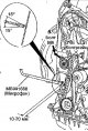
Adjusting the tension of the timing belt
1. Connect the microphone (belt tension measuring device) to the MUT-II. 2. Connect the MUT-II device to the diagnostic connector. 3. Remove the timing belt cover of the...
1. Connect the microphone (belt tension measuring device) to the MUT-II. 2. Connect the MUT-II device to the diagnostic connector. 3. Remove the timing belt cover of the...

Crankshaft pulley for poly V-belt drive
Removal Remove the lower engine splash shield. Loosen the bolt and remove the air conditioning hose clamp (Fig. 4.5). Fig. 4.5. Crankshaft pulley for poly V-belt drive:...
Removal Remove the lower engine splash shield. Loosen the bolt and remove the air conditioning hose clamp (Fig. 4.5). Fig. 4.5. Crankshaft pulley for poly V-belt drive:...

Camshaft and camshaft oil seal
Fig. 4.9. Camshaft and camshaft seal: 1 - camshaft pulley; 2 - rear upper timing belt cover; 3 - camshaft oil seal; 4 - brake booster vacuum hose; 5 - vacuum hose; 6 -...
Fig. 4.9. Camshaft and camshaft seal: 1 - camshaft pulley; 2 - rear upper timing belt cover; 3 - camshaft oil seal; 4 - brake booster vacuum hose; 5 - vacuum hose; 6 -...
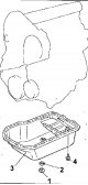
Oil pan
Removal Disconnect the cable from the negative battery terminal. Remove the lower engine splash shield. Remove the engine oil level indicator. Remove the plug and drain...
Removal Disconnect the cable from the negative battery terminal. Remove the lower engine splash shield. Remove the engine oil level indicator. Remove the plug and drain...

Crankshaft oil seals
Removal Disconnect the cable from the negative battery terminal. Front crankshaft oil seal Remove the timing belt of the gas distribution mechanism drive. Unscrew the...
Removal Disconnect the cable from the negative battery terminal. Front crankshaft oil seal Remove the timing belt of the gas distribution mechanism drive. Unscrew the...

Cylinder head
Fig.4.25. Cylinder head fastening elements: 1- oil supply pipe; 2 - oil return pipe; 3 - Oil return pipe gasket; 4 - sealing ring; 5 - cylinder head mounting bolt, 30 Nm...
Fig.4.25. Cylinder head fastening elements: 1- oil supply pipe; 2 - oil return pipe; 3 - Oil return pipe gasket; 4 - sealing ring; 5 - cylinder head mounting bolt, 30 Nm...

Toothed timing belt
Removal Disconnect the cable from the negative battery terminal. Remove the lower engine splash shield. Remove the engine mount bracket. Loosen the bolt and remove the...
Removal Disconnect the cable from the negative battery terminal. Remove the lower engine splash shield. Remove the engine mount bracket. Loosen the bolt and remove the...

Removal and installation the engine
Warning: In Figure 4.34, elements marked with an (*) must be pre-tightened during installation and finally tightened after the vehicle has been lowered onto its wheels....
Warning: In Figure 4.34, elements marked with an (*) must be pre-tightened during installation and finally tightened after the vehicle has been lowered onto its wheels....
Checking the turbocharger flap drive
1. Disconnect the vacuum hose from the turbocharger flap actuator pipe. 2. Connect a hand vacuum pump to the pipe. 3. Make sure that the valve drive rod moves smoothly...
1. Disconnect the vacuum hose from the turbocharger flap actuator pipe. 2. Connect a hand vacuum pump to the pipe. 3. Make sure that the valve drive rod moves smoothly...

Checking the electromagnetic valve
Note: When disconnecting the vacuum hose, mark its position so that the hose can be reconnected in its original position. 1. Disconnect the vacuum hose from the solenoid...
Note: When disconnecting the vacuum hose, mark its position so that the hose can be reconnected in its original position. 1. Disconnect the vacuum hose from the solenoid...

Air filter
Removal Disconnect the wires from the battery terminals. Release the spring clips and remove the air filter cover (Fig. 4.38). Fig. 4.38. Air filter: 1 - air filter...
Removal Disconnect the wires from the battery terminals. Release the spring clips and remove the air filter cover (Fig. 4.38). Fig. 4.38. Air filter: 1 - air filter...

Intercooler (Intercooler)
Removal Disconnect the wires from the battery terminals. Drain the coolant from the engine cooling system. Disconnect the hoses from the radiator. Disconnect the...
Removal Disconnect the wires from the battery terminals. Drain the coolant from the engine cooling system. Disconnect the hoses from the radiator. Disconnect the...

Intake and exhaust manifolds
Removal Disconnect the cable from the negative battery terminal. Remove the turbocharger. Disconnect the vacuum hoses from the vacuum receiver (Fig. 4.40). Fig. 4.40....
Removal Disconnect the cable from the negative battery terminal. Remove the turbocharger. Disconnect the vacuum hoses from the vacuum receiver (Fig. 4.40). Fig. 4.40....

Turbocharger — Description, Precautions, Removal, Checking, Installation
Description A turbocharger increases engine power by increasing the pressure in the intake manifold above atmospheric pressure. The turbocharger is driven by exhaust...
Description A turbocharger increases engine power by increasing the pressure in the intake manifold above atmospheric pressure. The turbocharger is driven by exhaust...
Lubrication system
The engine is lubricated under pressure by a pump driven by a chain from the crankshaft. The lubrication system includes a pressure reducing valve built into the pump, a...
The engine is lubricated under pressure by a pump driven by a chain from the crankshaft. The lubrication system includes a pressure reducing valve built into the pump, a...

Checking the engine oil level
The engine oil level is checked by the oil level indicator (dipstick) located on the front side of the engine. The oil level indicator (dipstick) passes through the...
The engine oil level is checked by the oil level indicator (dipstick) located on the front side of the engine. The oil level indicator (dipstick) passes through the...

Engine oil change
Periodic oil and oil filter changes are the most important preventative maintenance procedure. As engine oil ages, it becomes thin and contaminated, leading to premature...
Periodic oil and oil filter changes are the most important preventative maintenance procedure. As engine oil ages, it becomes thin and contaminated, leading to premature...

Replacing the oil filter
Remove the oil filler cap. Remove the oil drain plug from the oil pan and wait until all the oil drains into a container. Use a special wrench to remove the oil filter....
Remove the oil filler cap. Remove the oil drain plug from the oil pan and wait until all the oil drains into a container. Use a special wrench to remove the oil filter....

Exhaust gas system
Fig. 4.45. Exhaust system: 1 - main muffler; 2 - central exhaust pipe; 3 - catalytic converter; 4 - exhaust inlet pipe; 5 - gasket; 6 - rubber suspension; 7 - rubber...
Fig. 4.45. Exhaust system: 1 - main muffler; 2 - central exhaust pipe; 3 - catalytic converter; 4 - exhaust inlet pipe; 5 - gasket; 6 - rubber suspension; 7 - rubber...
This section is available on: russian, bulgarian, belarusian, ukrainian, serbian, croatian, romanian, polish, slovak, hungarian
Link in different formats to this section
TEXTHTMLBB Code
- General information
- User manual
- Maintenance
- Power unit
- Petrol engines 4G9
- Diesel engines FBQT
- Diesel engines F9Q
- Cooling system
- Injection system (MPI)
- Injection system (GDI)
- Engine electrical equipment
- Transmission
- Clutch
- Mechanical gearbox
- Automatic gearbox
- Chassis and running gear
- Steering
- Brake system
- Front suspension and shafts
- Rear suspension
- Body and interior
- Exterior (external elements)
- Interior (internal elements)
- Doors, locks and windows
- Air conditioner
- Electrical equipment
- Equipment and devices
- Headlights and lighting
- Electrical circuits
- General information
- User manual
- Maintenance
- Power unit
- Petrol engines 4G9
- Petrol engines 4G1
- Diesel engines F9Q1
- Cooling system
- Fuel injection system GDI
- Fuel injection system MPI
- Diesel supply system F9Q1
- Ignition system
- Diesel preheating
- Transmission
- Clutch
- Mechanical gearbox
- Automatic gearbox
- Chassis and running gear
- Suspension and drive shafts
- Brake system
- Steering
- Body and interior
- Exterior (external elements)
- Interior (internal elements)
- Doors, locks and windows
- Heating and air conditioning
- Electrical equipment
- Power devices
- Equipment and devices