



Contents: Removal ⤓ Installation ⤓
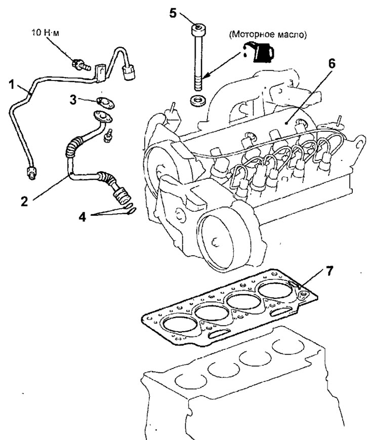
Fig.4.25. Cylinder head fastening elements: 1- oil supply pipe; 2 - oil return pipe; 3 - Oil return pipe gasket; 4 - sealing ring; 5 - cylinder head mounting bolt, 30 Nm + 100±4° + loosen + 25 Nm + 213±7°; 6 - cylinder head; 7 - cylinder head gasket
Removal
- Disconnect the cable from the negative battery terminal.
- Remove the lower engine splash shield.
- Reduce the pressure in the fuel system.
- Drain the coolant from the cooling system.
- Remove the plug and drain the engine oil from the engine.
- Remove the air filter and air intake pipe.
- Remove the catalytic converter.
- Remove the exhaust pipe and main muffler.
- Remove the timing belt of the gas distribution mechanism drive.
- Disconnect the connectors from the camshaft position sensor, fuel pressure sensor, high-pressure fuel pump, fuel temperature sensor, fuel injectors, glow plugs, coolant temperature sensor and EGR solenoid valve (Fig. 4.22).
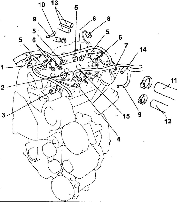
Fig. 4.22. Cylinder head: 1 - camshaft position sensor connector; 2 - fuel pressure sensor connector; 3 - high pressure fuel pump connector; 4 - fuel temperature sensor connector; 5 - fuel injector connector; 6 - glow plug connector; 7 - coolant temperature sensor connector; 8 - EGR solenoid valve connector; 9 - vacuum hose; 10 - brake booster vacuum hose; 11 - Upper radiator hose; 12 - engine cooling system hose; 13 - heater hoses; 14 - fuel return hose; 15 - fuel supply hose
- Loosen the clamp and disconnect the brake booster vacuum hose.
- Disconnect the vacuum hoses.
- Loosen the clamp and disconnect the upper radiator hose from the cooling system pipe.
- Loosen the clamp and disconnect the engine cooling system hose.
- Loosen the clamps and disconnect the heater hoses.
- Disconnect the fuel supply and return hoses. To prevent dirt and foreign matter from entering the fuel system, plug all open connections in the fuel system.
- Unscrew the bolt securing the oil supply pipe. Unscrew the connecting nuts and remove the oil supply pipe.
- Remove the two bolts and remove the oil return pipe and gasket
- Remove the O-rings from the bottom of the oil return tube.
- In the sequence shown in Figure 4.23, loosen and remove the cylinder head mounting bolts in 2 or 3 passes.
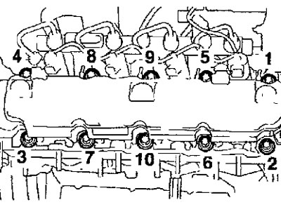
Fig. 4.23. Sequence of unscrewing the cylinder head mounting bolts
Warning: New cylinder head bolts must be used during installation.
- Carefully remove the cylinder head.
- Remove the cylinder head gasket.
- Cover the engine cylinders with a clean, lint-free cloth.
Installation
- Installation is carried out in the reverse order of removal, taking into account the following.
- Degrease the mating surfaces of the block and cylinder head.
- When installing, check that all holes on the gasket and cylinder head match.
- Install the gasket and cylinder head onto the cylinder block.
- In several stages, in the sequence shown in Figure 4.24, tighten the cylinder head mounting bolts
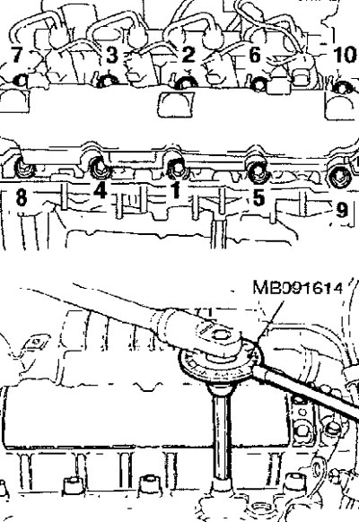
Fig. 4.24. Cylinder head bolt tightening sequence
Stages of tightening the cylinder head bolts:
1. Tighten the new bolts to 30 Nm in the sequence shown in Figure 4.24.
2. In the same sequence, tighten the bolts to an angle of 100±4°, for which install a special tool on the wrench that ensures that the bolts turn to a strictly defined angle.
3. Wait 3 minutes to allow the cylinder head gasket to seat.
4. Loosen bolts #1 and 2
5. Tighten bolts No.1 and 2 to 25 N·m.
6. Tighten bolts No.1 and 2 to an angle of 213±7°, for which install a special tool on the wrench that ensures that the bolts turn to a strictly defined angle.
7. Divide the remaining bolts into pairs: bolts #3 and 4, bolts #5 and 6, bolts #7 and 8, bolts #9 and 10. Tighten the bolt pairs according to the recommendations in steps 3, 4, and 5.
Warning: When tightening the cylinder head bolts, they stretch. If the cylinder head bolt is overtightened, replace it with a new one, do not re-tighten.
- Install the oil supply pipe and screw on the union nuts. Screw in the oil supply pipe mounting bolt.
- Install the oil return pipe and gasket.
- Remove the plugs and connect the fuel supply and return hoses.
- Connect the heater hoses and secure them with clamps.
- Connect the engine cooling system hose.
- Connect the upper radiator hose to the cooling system pipe.
- Connect the vacuum hoses.
- Connect the brake booster vacuum hose.
- Reconnect all previously disconnected electrical connectors.
- Connect the exhaust pipe and main muffler.
- Install the catalytic converter.
- Install the air filter and the air intake pipe.
- Install the timing belt to drive the gas distribution mechanism.
- Install the lower engine splash shield.
- Fill the engine with the required amount of recommended engine oil.
- Fill the cooling system with coolant.
- Connect the cable to the negative terminal of the battery.
- Start the engine and check for leaks.
The text of the article was obtained from the website (MITSUBISHIMAN)