



2.0L Engine Valve Cover and Components (item numbers are given in the order of assembly of the specified parts)
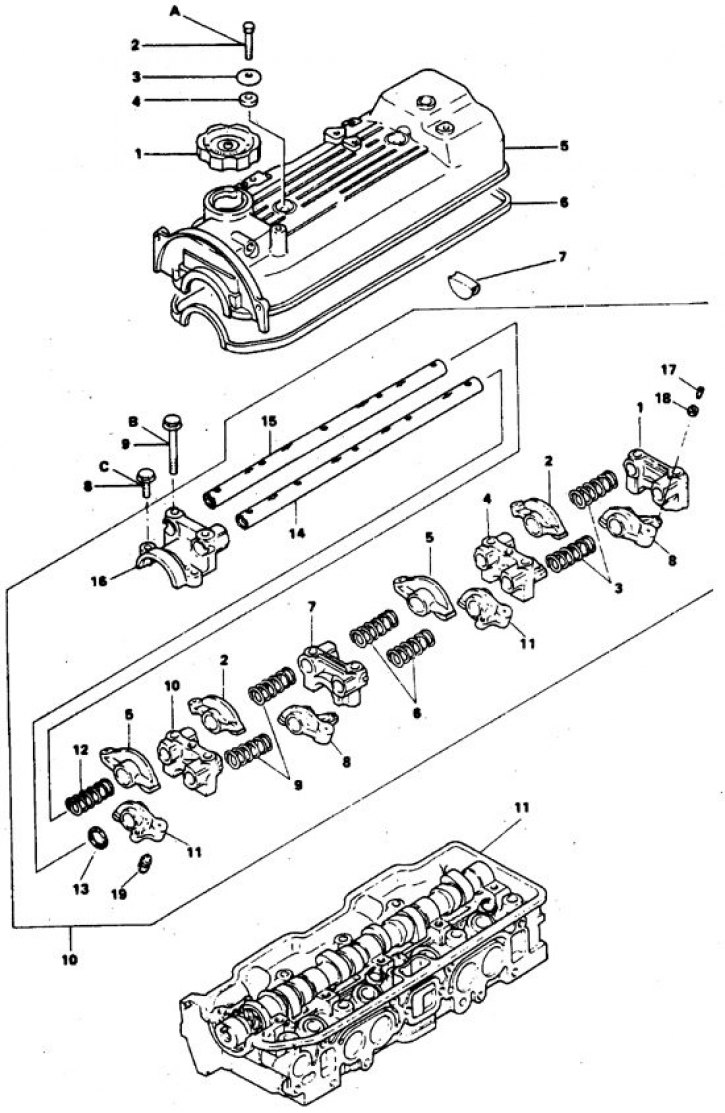
1. Cork; 2. Compaction; 3. Washer; 4. Bolt; 5. Lid; 6. Gasket; 7. Plug; 8, 9. Bolt; 10. Roller assembly with rocker arm; 11. Tightening torques (Nm): bolt A – 5–6, bolt B – 17–8, bolt C – 18–22.
Roller assembly with rocker arm:; 1, 4, 7, 10, 16. Camshaft bearing journal covers; 2, 5, 8, 1. Respectively: rocker arms D, C, B and A; 3, 6, 9, 12. Spring; 13. Spring flat washer; 14. Left rocker shaft; 15. Right roller; 17. Jet valve adjusting screw; 18. Lock nut; 19. Hydraulic pusher
2.4L Engine Cover and Air Vent
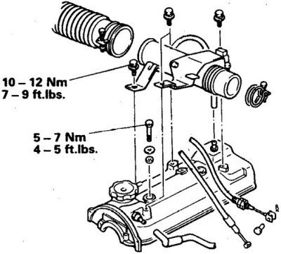
Cylinder head cover for 2.6L engine
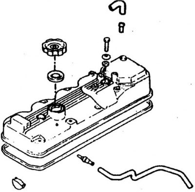
Cylinder head cover for 12-valve 3.0L engine
[The text of the article was obtained from the website mitsubishiman]
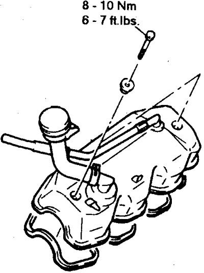
Cylinder head cover for 24-valve 3.0L engine
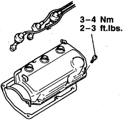
Cylinder head cover for a twin-shaft engine
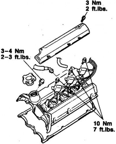
Removal
1. Disconnect the ground. Remove the air filter (on some injection engines it is enough to disconnect the air duct from the intake manifold).
2. Disconnect the ventilation hoses from the cover. To access the cover, move other hoses to the side; try not to disconnect hoses unless necessary.
3. Disconnect the wires from the spark plugs and set them aside. On twin shaft motors, use caution as the wires can be easily damaged.
4. If the cylinder head cover is located above the belt cover, then unscrew the cylinder head cover mounting bolts.
5. If the cylinder head cover is located under the belt cover, remove the belt cover, then unscrew the cylinder head cover bolts.
6. Carefully remove the lid; prying the lid is prohibited.
7. Remove the semi-circular plug at the back of the cover (or cylinder heads).
Installation
1. Clean the lid. Remove any remaining sealant from the plug and lid edges. If the cover gasket has not changed after removing the cover multiple times, replace it.
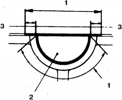
2. Before installation, lubricate the areas shown in the illustrations with sealant: (1 – areas where sealant is applied, 2 – plug, 3 – lubricate the areas of the cylinder head 10 mm from the edges of the plug with sealant).
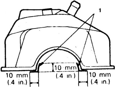
3. On V6 engines, apply sealant to the corner gasket (1 - sealant application area).
4. Then assembly is carried out in reverse order. When tightening the bolts, press the cover lightly. Tighten the cover bolts to 4.0–5.4 N·m. The engine can be started after 2 hours. If leaks are observed, remove the cover and determine the cause.