



Share with friends:
Vehicle power and exhaust system Mitsubishi Pajero 1 and 2

Power supply system — general information
The fuel system includes a rotary high-pressure fuel pump (HPFP), which is driven by a camshaft drive belt, injectors, a turbocharger, a fuel filter with a fuel pump,...
The fuel system includes a rotary high-pressure fuel pump (HPFP), which is driven by a camshaft drive belt, injectors, a turbocharger, a fuel filter with a fuel pump,...

Removal air from the fuel system
Elements of the power supply system 1. Fuel filter; 2. Blow-off screw; 3. Manual fuel priming pump; 4. Water in fuel sensor; 5. Water in fuel sensor connector Air filter...
Elements of the power supply system 1. Fuel filter; 2. Blow-off screw; 3. Manual fuel priming pump; 4. Water in fuel sensor; 5. Water in fuel sensor connector Air filter...
Removal water from the fuel filter
If the indicator light in the instrument cluster lights up to indicate the presence of water in the fuel, drain it from the filter using the following sequence: unscrew...
If the indicator light in the instrument cluster lights up to indicate the presence of water in the fuel, drain it from the filter using the following sequence: unscrew...

Replacing the fuel filter element
Fuel filter 1. Fuel drain pipe to the tank; 2. Fuel supply pipeline; 3. Filter element; 4. Bracket; 5. Manual fuel priming pump; 6. Blow-off screw; 7. Water in fuel...
Fuel filter 1. Fuel drain pipe to the tank; 2. Fuel supply pipeline; 3. Filter element; 4. Bracket; 5. Manual fuel priming pump; 6. Blow-off screw; 7. Water in fuel...

Removal and installation of fuel injection pump
High pressure fuel pump 1. Fuel injection pump; 2. Toothed pulley of pump drive; 3. Speed sensor; 4. Fuel supply corrector hose for boost pressure; 5. High pressure...
High pressure fuel pump 1. Fuel injection pump; 2. Toothed pulley of pump drive; 3. Speed sensor; 4. Fuel supply corrector hose for boost pressure; 5. High pressure...
Idle speed adjustment
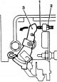
1. Adjustment of the engine idle speed must be performed on a warm engine, with adjusted clearances in the valve timing mechanism, with the initial injection advance...
1. Adjustment of the engine idle speed must be performed on a warm engine, with adjusted clearances in the valve timing mechanism, with the initial injection advance...

Checking the pre-heating system of the 4D56T engine
Electrical diagram of the accelerated pre-heating system of the 1D56T engine 1. Make sure the battery voltage is between 11-13V. 2. Make sure that the coolant...
Electrical diagram of the accelerated pre-heating system of the 1D56T engine 1. Make sure the battery voltage is between 11-13V. 2. Make sure that the coolant...
Checking the pre-heating control unit
1. Make sure the control unit connector is securely fastened. 2. Connect terminal "10" of the control unit to ground. 3. Check the voltage at the control unit terminals....
1. Make sure the control unit connector is securely fastened. 2. Connect terminal "10" of the control unit to ground. 3. Check the voltage at the control unit terminals....
Checking the spark plug relay
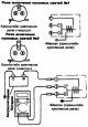
Scheme of testing the relay of inclusion of starting spark plugs of the side 1. Use an ohmmeter to check the integrity of the circuit between terminal "C" of the spark...
Scheme of testing the relay of inclusion of starting spark plugs of the side 1. Use an ohmmeter to check the integrity of the circuit between terminal "C" of the spark...
Turbocharger — removal, inspection and installation
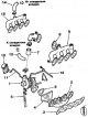
Intake and exhaust manifolds and turbocharger 1. Turbocharger; 2. Exhaust manifold; 3. Gasket; 4. Thermal insulation shield; 5. Oil drain pipe; 6. Gasket between...
Intake and exhaust manifolds and turbocharger 1. Turbocharger; 2. Exhaust manifold; 3. Gasket; 4. Thermal insulation shield; 5. Oil drain pipe; 6. Gasket between...

Checking the boost pressure
Caution! The boost pressure test must be performed by two testers in a location where the vehicle can accelerate with the accelerator pedal fully depressed. Attention!...
Caution! The boost pressure test must be performed by two testers in a location where the vehicle can accelerate with the accelerator pedal fully depressed. Attention!...

Air-to-air cooler — removal and installation
Air to air cooler 1. Heat exchanger; 2. Electric fan; 3. Protective cover; 4. Air duct connecting the cooler to the intake manifold; 5. Air duct connecting the...
Air to air cooler 1. Heat exchanger; 2. Electric fan; 3. Protective cover; 4. Air duct connecting the cooler to the intake manifold; 5. Air duct connecting the...

Exhaust gas system-design
Exhaust system 1. Intake pipe; 2. Additional muffler; 3. Main muffler Exhaust system 4D56T A - long wheelbase vehicles; B – short-base vehicles; 1. Intake pipe; 2....
Exhaust system 1. Intake pipe; 2. Additional muffler; 3. Main muffler Exhaust system 4D56T A - long wheelbase vehicles; B – short-base vehicles; 1. Intake pipe; 2....

Locations of power supply system components and assemblies
Location of fuel system components of the 24-valve 3.0L engine, 1995 F. Air conditioning compressor relay; Q. Air conditioner switch; G. Camshaft rotation sensor; P....
Location of fuel system components of the 24-valve 3.0L engine, 1995 F. Air conditioning compressor relay; Q. Air conditioner switch; G. Camshaft rotation sensor; P....
This section is available on: russian, bulgarian, belarusian, ukrainian, serbian, croatian, romanian, polish, slovak, hungarian
Link in different formats to this section
TEXTHTMLBB Code
- General information
- User manual
- Troubleshooting
- Maintenance
- Technical specifications
- Power unit
- Engine repair
- Cooling system
- Lubrication system
- Fuel system
- Engine management system
- Intake and exhaust system
- Engine electrical equipment
- Transmission
- Clutch
- Manual gearbox
- Automatic gearbox
- Drive shafts
- Chassis and running gear
- Front suspension
- Rear suspension
- Brake system
- Steering
- Body and interior
- Exterior (external elements)
- Interior (internal elements)
- Doors, locks and windows
- Body dimensions
- Electrical equipment
- Safety system (SRS)
- Air conditioner
- Equipment and devices
- Electrical diagrams
- General information
- User manual
- Seats and seat belts
- Instruments and controls
- Driving and operation
- Maintenance
- Power unit
- Gasoline engines
- Diesel engines
- Ignition system
- Engine electrical equipment
- Cooling and lubrication system
- Power and exhaust system
- Fuel system (gasoline)
- Fuel system (diesel)
- Transmission
- Clutch
- Mechanical gearbox
- Automatic gearbox
- Drive shafts and axles
- Chassis and running gear
- Front suspension
- Rear suspension
- Steering
- Brake system
- Body and interior
- Exterior (external elements)
- Interior (internal elements)
- Doors, locks and windows
- Electrical equipment
- Equipment and devices
- Heater and air conditioner
- Cruise control
- Headlights and lighting
- Electrical circuits