
High pressure fuel pump
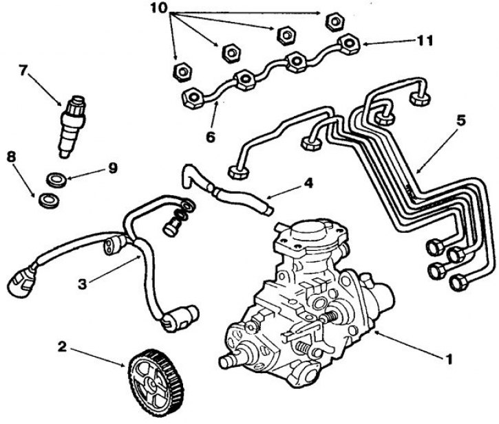
1. injection pump; 2. pump drive pulley; 3. Speed sensor; 4. Hose of the fuel supply corrector for boost pressure; 5. High pressure pipelines; 6. Fuel drain pipelines; 7. Nozzle; 8. Nozzle gasket; 9. Injector body gasket; 10. Laying the fuel drain pipeline; 11. Fuel drain pipe nut
Removing
1. Disconnect the wires from the battery terminals.
2. On vehicles with an air-to-air heat exchanger, disconnect the electrical wires from the cooler electric fan, disconnect the air hoses from the cooler, unscrew the four arc mounting bolts and remove the entire assembly.
3. Disconnect the turbo boost hose.
4. Disconnect the electrical wires from the pump (see fig. High pressure fuel pump).
5. Disconnect the fuel inlet and outlet pipes, fuel control cable and high pressure pipes from the pump.
6. Remove the top cover of the timing gear.
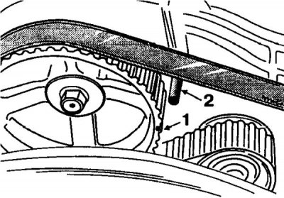
7. Rotating the crankshaft clockwise with a key on the pulley mounting bolt, align the marks on the camshaft pulley (1) and pulley of the high-pressure fuel pump drive with dowel pins (2) on the block and loosen the toothed belt tension.
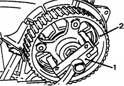
8. Turn away a nut of fastening of a gear pulley of a drive of TNVD and remove a pulley (2) with a puller (1). Loosen the two front bolts securing the injection pump.
9. Remove the rear pump mounting bracket, then remove the injection pump.
Installation
1. Install the two front pump mounting bolts and reinstall the rear pump mounting bracket.
2. Install the gear pulley of the injection pump drive, screw on and tighten the pulley nut to a torque of 8.0–9.0 kgf/m.
3. Put a toothed belt on the injection pump drive pulley, after aligning the alignment marks.
4. Adjust the initial fuel injection advance angle of the injection pump as described below.
Tighten the pump mounting bolts.
5. Establish the top cover of a drive of the gas-distributing mechanism.
6. Connect the high pressure pipes, fuel control cable, fuel inlet and outlet pipes to the pump.
7. Connect the hose to the fuel pressure corrector for the boost pressure of the pump.
8. Connect the electrical wires to the pump.
9. Replace the air/air heat exchanger, if present.
10. Connect the wires to the battery terminals.
11. Start the engine and check its operation at idle.
Adjustment of the initial angle of advancing the fuel injection pump
1. Turning the crankshaft clockwise with a key on the pulley mounting bolt, set the piston of the 1st cylinder to the TDC of the end of the compression stroke.
2. In this case, the mark on the crankshaft pulley should be opposite the TDC mark ("TDC") on the bottom cover of the timing gear drive.
3. Remove the screw plug located at the back of the pump between the high pressure pipe fittings.
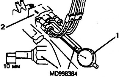
4. Screw the post MD 998384 into the hole for the plug, after making sure that its movable pin protrudes 10 mm (1 - indicator, 2 - injection pump).
5. Attach the indicator to the end of the post.
6. Turn the crankshaft counterclockwise so that the piston of the 1st cylinder is set at about 30°to TDC.
7. In this position, set the indicator needle to zero. Slightly turning the crankshaft in both directions, make sure that the indicator arrow does not respond.
8. Otherwise, repeat the previous operation.
9. Turning the crankshaft clockwise, align the mark corresponding to the fuel injection advance angle by 2°, 5°and 7°after TDC (depending on engine model), on the crankshaft pulley with the alignment mark on the bottom cover of the timing gear.
10. In this position, the indicator should show 1±0.03 mm.
11. If the indicator shows a different value, then loosen the two front pump mounting bolts and the pump rear bracket mounting bolts.
12. Loosen the high pressure fittings.
13. If the indicator reading is less than the required value, move the pump towards the engine and vice versa.
14. Tighten the front pump mounting bolts and the pump rear bracket mounting bolts.
15. Tighten the high pressure fittings.
16. Remove the indicator and unscrew the indicator column from the pump.
17. Screw a screw plug into the pump hole, after replacing the gasket.