
Intake and exhaust manifolds and turbocharger
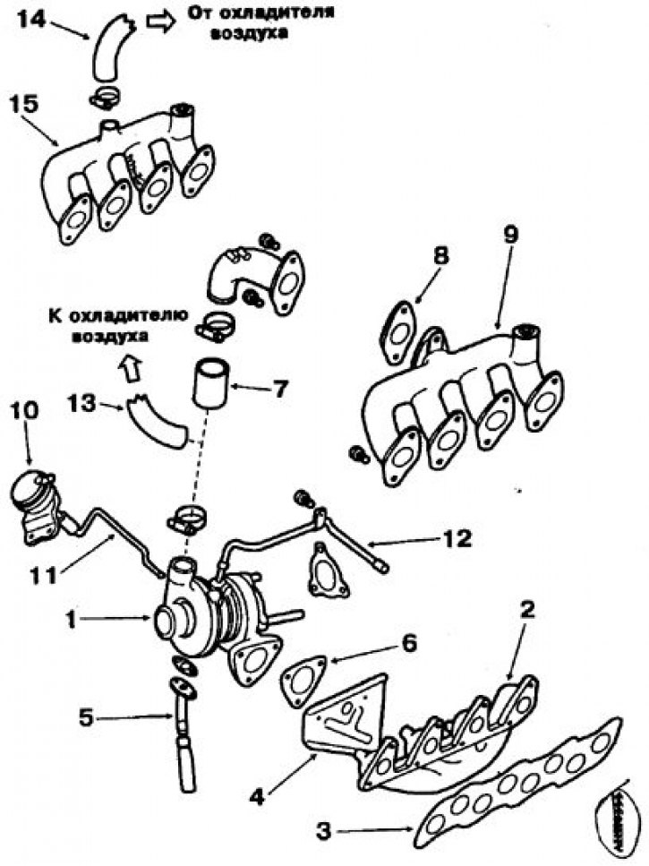
1. Turbocharger; 2. Exhaust manifold; 3. Gasket; 4. Heat shield; 5. Oil outlet pipeline; 6. Gasket between turbocharger and exhaust manifold; 7. Air duct connecting the turbocharger to the intake manifold; 8. Gasket; 9. Inlet manifold of engines without air cooler; 10. Pneumatic drive; 11. Boost regulator control rod; 12. Oil supply pipeline; 13. Air duct connecting the turbocharger to the air cooler; 14. Air duct connecting the cooler to the intake manifold; 15. Intake manifold of engines with an air cooler
Checking the pneumatic drive of the boost controller
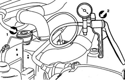
1. Pneumatic drive
2. Manual vacuum pump with pressure gauge
Removing
1. Disconnect and remove the battery.
2. On vehicles with engines equipped with an air-to-air cooler, remove the cooler as follows. Remove the two side heat shields.
3. Disconnect the hose from the boost control actuator.
4. Disconnect the hose from the boost pressure corrector.
5. Remove the top heat shield.
6. Remove the boost control actuator.
7. Remove the intake manifold.
8. Disconnect the oil supply line from the turbocharger.
9. Disconnect from a turbocharger a pipe of a supply of the fulfilled gases.
10. Remove the heat shield from the exhaust manifold.
11. Turn away three bolts of fastening of a turbocharger to a final collector.
12. Disconnect the oil outlet hose from the pump nozzle.
13. Remove the turbocharger.
14. Remove the exhaust manifold with gasket.
Installation
1. Installation of the turbocharger is carried out in the reverse order of removal, with the replacement of all gaskets with new ones and in compliance with the prescribed tightening torques.
2. After installing the turbocharger, perform the following operations:
- check the operation of the boost controller pneumatic drive;
- Disconnect the vacuum hose from the pneumatic actuator and connect the fitting of the hose of the manual vacuum pump with a pressure gauge to the pneumatic actuator branch pipe.
3. Using the pump to pressurize, use the pressure gauge to determine the pressure at which the boost control actuator rod will move approximately 1 mm.
4. The pressure gauge reading must match the boost pressure value.
5. If the value obtained is slightly different from the normal value, check the boost control and boost pressure valve and replace them if necessary.
Attention! On the 4D56T engine, in order to avoid damage to the pneumatic drive diaphragm, do not create excess pressure of more than 0.9 kgf / cm2.
7. Check the oil level in the crankcase.
8. Disconnect the wires from the engine stop solenoid valve on the injection pump and, while cranking the engine with a starter, pump the lubrication system until the oil pressure control lamp goes out.
9. Connect the wires to the engine stop solenoid valve, start the engine and let it run for a while to make sure it works properly.