Preliminary operations
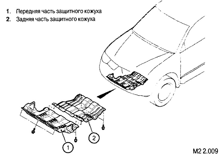
1. Remove the front and rear parts of the lower protective cover of the engine compartment (see Fig. M2 2.009).
2. Remove the hood.
3. Remove the windshield wiper mechanism assembly (see Fig. M2 2.010).
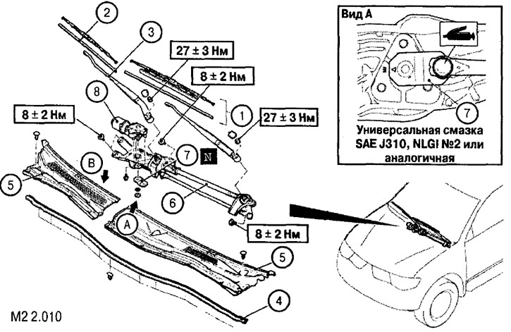
Removal the windshield wiper mechanism: 1. Windscreen wiper blade assembly; 2. Rubber element of the brush; 3. Windscreen wiper arm; 4. Hood seal; 5. Overlays; 6. Drive mechanism; 7. Mounting plate; 8. Electric drive
* The elements are removed in the order of the numbers shown in the figure
4. Disconnect and remove the battery.
5. Remove the air filter elements (see Fig. M2 2.011).
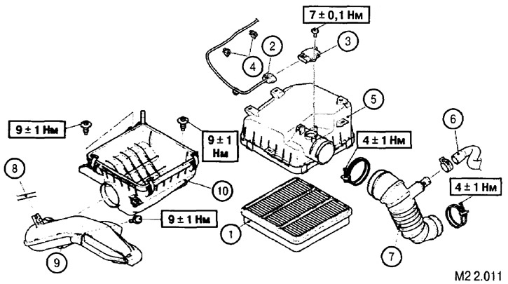
Removal the air filter elements: 1. Filter element; 2. Air flow meter connector; 3. Air flow meter; 4. Clamp the harness; 5. Air filter cover; 6. Breather hose; 7. Air duct; 8. Radiator expansion tank hose; 9. Air duct; 10. Air filter housing
* The elements are removed in the order of the numbers shown in the figure
Information copied from the website (MitsubishiMan.ru)
6. Drain the coolant and engine oil.
7. Disconnect and remove the cooling system components (pipes, expansion tank, radiator, air conditioner condenser, etc.) (see Fig. M2 2.012).
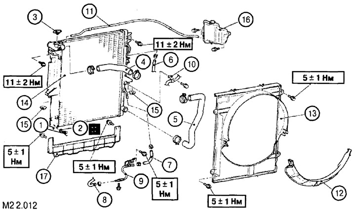
Removal the cooling system components: 1. Drain plug; 2. Sealing ring; 3. Radiator cap; 4. Upper branch pipe; 5. Lower branch pipe; 6. Oil cooler feed hose (automatic transmission); 7. Oil cooler feed pipe (automatic transmission); 8. Return pipe of oil cooler (automatic transmission); 9. Oil cooler return pipe (automatic transmission); 10. Feed hose clamp (automatic transmission); 11. Expansion tank hose; 12. Lower fan casing; 13. Cooling fan shroud; 14. Radiator; 15. Lower radiator support; 16. Expansion tank; 17. Bottom panel (air flow guide)
* The elements are removed in the order of the numbers shown in the figure.
8. Remove the radiator cooling fan elements (see Fig. M2 2.013).
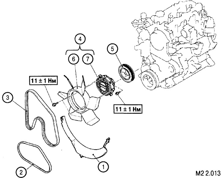
Removal drive belts and fan: 1. Lower fan casing; 2. Air conditioning compressor drive belt; 3. Generator and power steering pump drive belt; 4. Fan impeller and clutch assembly; 5. Coolant pump pulley; 6. Fan impeller; 7. Fan clutch
* The elements are removed in the order of the numbers shown in the figure
9. Next, disconnect and remove the elements indicated in the figure (see Fig. M2 2.014).
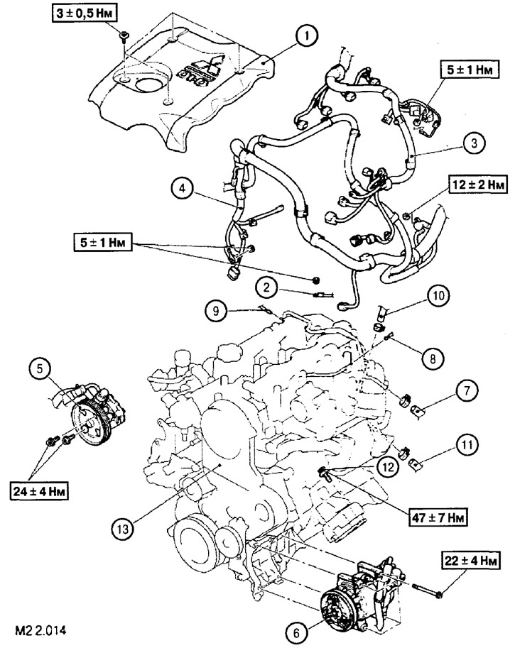
1. Engine cover; 2. Ground connection terminal; 3. Control unit wiring harness; 4. Battery wiring harness; 5. Steering oil pump assembly; 6. Air conditioning compressor assembly; 7. Brake booster hose; 8. Brake booster sensor pipe; 9. Vacuum hose of the front wheel drive disconnect solenoid valve; 10. Fuel supply hose; 11. Return fuel hose; 12. Front engine mount mounting screw; 13. Engine assembly
* The elements are removed in the order of the numbers shown in the figure
Note: The power steering pump (5) and the air conditioning compressor (6) are removed as an assembly without disconnecting the corresponding lines. After removal from the engine, they must be suspended and secured in the engine compartment so that they do not interfere with the removal and subsequent installation of the engine assembly. Note: After disconnecting the return fuel line (11) and before removing the front mount fastening screws (12), it is necessary to disconnect and remove the exhaust system components and the EGR system and the transmission fastening and control components (propeller shaft, clutch drive, manual transmission, automatic transmission oil control and cooling elements). A description of these operations is given in the relevant sections of this book.
It is also necessary to jack up the engine from below.
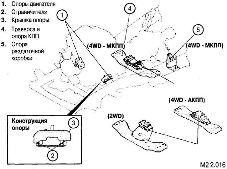
10. Disconnect the power unit from the supports.
11. Once again, carefully check that all connected elements are disconnected from the engine and that nothing interferes with its removal.
12. Having securely fastened the cable to the engine, using the winch (1), carefully remove the engine assembly from the engine compartment.
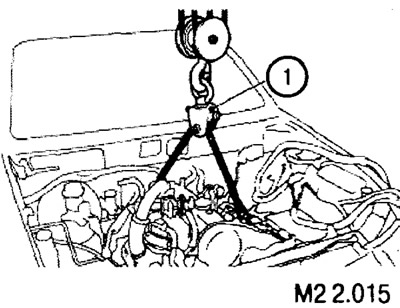
Installation is carried out in the reverse order of removal, followed by all necessary checks and adjustments.