
Share with friends:
Diesel car engine Mitsubishi L200 4

General information about diesel engines
The 4D56 D-DI engine is a modification of the 4D56 and 4D56T engines that were previously used on Mitsubishi cars of the L-200 Strada, L-300 Delica, Pajero models. The...
The 4D56 D-DI engine is a modification of the 4D56 and 4D56T engines that were previously used on Mitsubishi cars of the L-200 Strada, L-300 Delica, Pajero models. The...
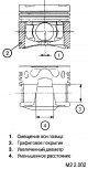
Distinctive features of the 4D56 D-DI engine from 4D56 and 4D56T
In order to reduce the number of components and manufacturability, this cylinder block does not have liners. In previous designs, thin-walled dry-type sleeves were used....
In order to reduce the number of components and manufacturability, this cylinder block does not have liners. In previous designs, thin-walled dry-type sleeves were used....

Conventions used in text and figures
- a part that must be replaced with a new one when assembling a unit or mechanism; - the part to which engine oil is applied during assembly; - a part on which a sealant...
- a part that must be replaced with a new one when assembling a unit or mechanism; - the part to which engine oil is applied during assembly; - a part on which a sealant...

Tightening torques for standard fasteners
Standard fasteners used on the vehicle (screws, bolts, nuts) have metric threads and electroplated (zinc). On the screw heads (bolts) there is a marking that allows you...
Standard fasteners used on the vehicle (screws, bolts, nuts) have metric threads and electroplated (zinc). On the screw heads (bolts) there is a marking that allows you...

Removal and installation of the power unit
Preliminary Operations 1. Remove the front and rear of the lower engine compartment guard (see fig. M2 2.009). 2. Remove the hood. 3. Remove the wiper mechanism assembly...
Preliminary Operations 1. Remove the front and rear of the lower engine compartment guard (see fig. M2 2.009). 2. Remove the hood. 3. Remove the wiper mechanism assembly...
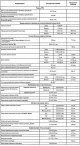
Diesel engine specifications
Parameters to be checked (regulation) during repairs or maintenance (during maintenance) works Diameters in the cylinder head for installing parts of repair dimensions
Parameters to be checked (regulation) during repairs or maintenance (during maintenance) works Diameters in the cylinder head for installing parts of repair dimensions

Auxiliary drive belts and pulley
Note: after assembly, the tension of the belts must be checked (1) And (2) and adjust the belt tension if necessary (2). Due to the presence of an automatic tensioner,...
Note: after assembly, the tension of the belts must be checked (1) And (2) and adjust the belt tension if necessary (2). Due to the presence of an automatic tensioner,...

Toothed drive belts — design description
This engine uses two types of timing belts: toothed timing belt; toothed belt drive balancer shafts (next: belt «IN»). 1. Oil pipe; 2. Oil pipe; 3. Oil pipe; 4. Vacuum...
This engine uses two types of timing belts: toothed timing belt; toothed belt drive balancer shafts (next: belt «IN»). 1. Oil pipe; 2. Oil pipe; 3. Oil pipe; 4. Vacuum...

Removing the timing belt
Features of the work Note: if you plan to continue using this belt, before removing it, put an arrow on its non-working surface with chalk indicating the direction of...
Features of the work Note: if you plan to continue using this belt, before removing it, put an arrow on its non-working surface with chalk indicating the direction of...

Removal and installation of the injection pump pulley
Using a special holder (1), unscrew the nut securing the pulley. After installing the gear, tighten the nut to 64±5 Nm. The pulley is removed from the shaft using a set...
Using a special holder (1), unscrew the nut securing the pulley. After installing the gear, tighten the nut to 64±5 Nm. The pulley is removed from the shaft using a set...

Removal and installation of a belt «B» of a drive of balancing shafts
1. Crankshaft pulley; 2. flange; 3. Belt «IN»; 4. Tensioner sleeve; 5. Tension spring; 6. Tensioner assembly Removing the belt «IN» Note: if you plan to continue using...
1. Crankshaft pulley; 2. flange; 3. Belt «IN»; 4. Tensioner sleeve; 5. Tension spring; 6. Tensioner assembly Removing the belt «IN» Note: if you plan to continue using...

Removal and installation of balancer shaft pulleys
Removal and installation of a pulley of the right balancing shaft Remove the plug from the right side of the cylinder block, insert into the hole (A) Phillips...
Removal and installation of a pulley of the right balancing shaft Remove the plug from the right side of the cylinder block, insert into the hole (A) Phillips...

Timing Belt Tensioner
After removing the automatic tensioner, check it for leaks. Check the wear of the end of the rod and measure the amount of its protrusion from the mechanism. If there...
After removing the automatic tensioner, check it for leaks. Check the wear of the end of the rod and measure the amount of its protrusion from the mechanism. If there...

Timing belt installation
Reinstall the automatic tensioner mechanism, the lever with the roller and, aligning the pulley marks, put the belt on the pulleys (without sagging) in the following...
Reinstall the automatic tensioner mechanism, the lever with the roller and, aligning the pulley marks, put the belt on the pulleys (without sagging) in the following...

Removal and installation of a valvate cover
1. Branch pipe of the oil separation system; 2. Filler cap; 3. Oil seal of the nozzle body; 4. Oil inlet fuel pipe; 5. Valve cover; 6. Gasket «A»; 7. Gasket «IN»; 8....
1. Branch pipe of the oil separation system; 2. Filler cap; 3. Oil seal of the nozzle body; 4. Oil inlet fuel pipe; 5. Valve cover; 6. Gasket «A»; 7. Gasket «IN»; 8....

Removing the cylinder head
Preliminary Operations 1. Disconnect and remove the battery. 2. Drain coolant and engine oil. 3. Disconnect and remove the air filter elements. 4. Remove the throttle...
Preliminary Operations 1. Disconnect and remove the battery. 2. Drain coolant and engine oil. 3. Disconnect and remove the air filter elements. 4. Remove the throttle...

Installing the cylinder head gasket
Attention: before installing a new gasket, clean and degrease the surfaces of the cylinder head and cylinder block. Make sure there are no foreign objects (remnants of...
Attention: before installing a new gasket, clean and degrease the surfaces of the cylinder head and cylinder block. Make sure there are no foreign objects (remnants of...
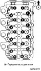
Installing the cylinder head
Before installation, clean and degrease the surfaces of the cylinder head and BC, install the gasket, head and screws with washers. Note: check the number of marks...
Before installation, clean and degrease the surfaces of the cylinder head and BC, install the gasket, head and screws with washers. Note: check the number of marks...

Removal and installation of camshafts
Note: an asterisk marks the parts removed and installed when replacing valve stem seals (28). In this case, when removing the valve crackers, it is necessary to set the...
Note: an asterisk marks the parts removed and installed when replacing valve stem seals (28). In this case, when removing the valve crackers, it is necessary to set the...

Disassembly and assembly of the valve mechanism
Elements of the cylinder head valve mechanism: 1. Cylinder head screws; 2. Washer; 3. cylinder head assembly; 4. Cylinder head gasket; 5. Valve crackers; 6. Valve spring...
Elements of the cylinder head valve mechanism: 1. Cylinder head screws; 2. Washer; 3. cylinder head assembly; 4. Cylinder head gasket; 5. Valve crackers; 6. Valve spring...

Restoration of the geometric characteristics of the valve seat
1. Check the clearance between the valve guide and the valve stem before performing any valve seat adjustment work. 2. Using a set of cutters, machine the seat according...
1. Check the clearance between the valve guide and the valve stem before performing any valve seat adjustment work. 2. Using a set of cutters, machine the seat according...

Valve seat replacement
Note: Valve seat replacement must be done using machine tools. Before replacing the seat, check and, if necessary, replace the valve guide. 1. Cut off the inside of the...
Note: Valve seat replacement must be done using machine tools. Before replacing the seat, check and, if necessary, replace the valve guide. 1. Cut off the inside of the...

Valve Guide Replacement
1. Using a press, remove the old guide bushing. Attention: do not use a new bushing of the same size as the old one to replace. Apply the bushing of the next repair...
1. Using a press, remove the old guide bushing. Attention: do not use a new bushing of the same size as the old one to replace. Apply the bushing of the next repair...

Rocker assembly
1. When installing the rocker assembly, pre-set the protrusion of the adjusting screw within 5.5-6.5 mm. 2. Lubricate the contact surfaces with a thin layer of engine...
1. When installing the rocker assembly, pre-set the protrusion of the adjusting screw within 5.5-6.5 mm. 2. Lubricate the contact surfaces with a thin layer of engine...

Installing the exhaust camshaft assembly
1. Before installation, lubricate the contact surfaces of the camshaft (necks, cams and gears) thin layer of engine oil (see fig. M2 2.092). 2. Install the camshaft in...
1. Before installation, lubricate the contact surfaces of the camshaft (necks, cams and gears) thin layer of engine oil (see fig. M2 2.092). 2. Install the camshaft in...

Installing the exhaust camshaft bearing caps
1. Install the bearing caps and tighten, without tightening, the fixing screws. 2. After lubricating the O-ring with engine oil, install the oil line. Attention: when...
1. Install the bearing caps and tighten, without tightening, the fixing screws. 2. After lubricating the O-ring with engine oil, install the oil line. Attention: when...

Installation of an additional gear wheel of a camshaft of inlet valves
1. When installing the gear, hold the camshaft by the hexagon wrench. 2. Install the pins in the camshaft gear and additional gear as shown. 3. Install the C-spring into...
1. When installing the gear, hold the camshaft by the hexagon wrench. 2. Install the pins in the camshaft gear and additional gear as shown. 3. Install the C-spring into...

Installing the intake camshaft assembly
1. Install all intake valve rockers. 2. Lubricating the working surfaces of the camshaft (necks, cams and gear teeth) with a small amount of engine oil, install the...
1. Install all intake valve rockers. 2. Lubricating the working surfaces of the camshaft (necks, cams and gear teeth) with a small amount of engine oil, install the...

Installing the intake camshaft covers
1. When installing the front bearing cap, apply 3M ATD N® 8660 or equivalent. Note: The cover must be installed within 3 minutes after the sealant has been applied. 2....
1. When installing the front bearing cap, apply 3M ATD N® 8660 or equivalent. Note: The cover must be installed within 3 minutes after the sealant has been applied. 2....

Checking and adjusting camshafts and valves
Camshaft Lobe Dimensions Standard value, mm: intake camshaft: 35.47; exhaust camshaft: 35.41. Maximum allowable value, mm: intake camshaft: 34.97; exhaust camshaft:...
Camshaft Lobe Dimensions Standard value, mm: intake camshaft: 35.47; exhaust camshaft: 35.41. Maximum allowable value, mm: intake camshaft: 34.97; exhaust camshaft:...
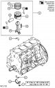
Connecting rod and piston group — design description
Connecting rod and piston group: 1. Nut; 2. Connecting rod cover; 3. Bottom liner; 4. Piston and connecting rod assembly; 5. Top liner; 6. Compression ring No. 1; 7....
Connecting rod and piston group: 1. Nut; 2. Connecting rod cover; 3. Bottom liner; 4. Piston and connecting rod assembly; 5. Top liner; 6. Compression ring No. 1; 7....

Removing connecting rod caps
Mark before removing connecting rod caps (belonging to the cylinder) on the side surface of the lower head of the connecting rod.
Mark before removing connecting rod caps (belonging to the cylinder) on the side surface of the lower head of the connecting rod.

Extraction of the piston with a rod in gathering
In order not to damage the cylinder mirror, put plastic safety tubes on the connecting rod bolts (2) and remove the piston and connecting rod from the cylinder. Note:...
In order not to damage the cylinder mirror, put plastic safety tubes on the connecting rod bolts (2) and remove the piston and connecting rod from the cylinder. Note:...

Assembly of connecting rod, piston, pin, piston rings
Attention: if the piston or pin is being replaced, pay attention to the marking (size group), applied on the plane of the cylinder block and the piston crown, in...
Attention: if the piston or pin is being replaced, pay attention to the marking (size group), applied on the plane of the cylinder block and the piston crown, in...

Installation of oil scraper and compression rings
Installing the oil scraper ring Install the ring expander and ring into the piston groove. Installation of compression rings Using special pliers, first install ring No....
Installing the oil scraper ring Install the ring expander and ring into the piston groove. Installation of compression rings Using special pliers, first install ring No....

Checking piston rings
Attention: if the piston is replaced with a new one, the piston rings must also be replaced with new ones. Check piston rings for damage, kinks or significant wear....
Attention: if the piston is replaced with a new one, the piston rings must also be replaced with new ones. Check piston rings for damage, kinks or significant wear....
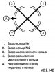
Piston and connecting rod assembly installation
Position the compression ring gaps, expander gap, and oil scraper gap as shown. Rotate the crankshaft until the connecting rod journal of the respective cylinder is at...
Position the compression ring gaps, expander gap, and oil scraper gap as shown. Rotate the crankshaft until the connecting rod journal of the respective cylinder is at...

Tightening the connecting rod cap nuts
1. Lubricate the threads of the connecting rod bolts and, after installing the covers, hand-tighten the fastening nuts (successively, in several steps). 2. Tighten the...
1. Lubricate the threads of the connecting rod bolts and, after installing the covers, hand-tighten the fastening nuts (successively, in several steps). 2. Tighten the...

Determining bearing clearance using a plastic gauge
1. Remove oil from the bearing surface and the crankshaft journal. 2. Cut off a piece of plastic gauge (1), the length of which corresponds to the width of the liner,...
1. Remove oil from the bearing surface and the crankshaft journal. 2. Cut off a piece of plastic gauge (1), the length of which corresponds to the width of the liner,...

Removal and installation of elements of the block of cylinders
1. Flywheel screw (manual transmission-2WD); 2. Ball bearing (manual transmission-2WD); 3. Flywheel (MKnn-2WD); 4. Flywheel screw (Manual-4WD); 5. Ball bearing...
1. Flywheel screw (manual transmission-2WD); 2. Ball bearing (manual transmission-2WD); 3. Flywheel (MKnn-2WD); 4. Flywheel screw (Manual-4WD); 5. Ball bearing...

Replacing the crankshaft seals
Installation of a forward epiploon of a cranked shaft Put the guide on the shaft (pilot sleeve) (3) and lubricate it with a thin layer of engine oil. With the help of a...
Installation of a forward epiploon of a cranked shaft Put the guide on the shaft (pilot sleeve) (3) and lubricate it with a thin layer of engine oil. With the help of a...
This section is available on: russian, bulgarian, belarusian, ukrainian, serbian, croatian, romanian, polish, slovak, hungarian
Similar materials for other Mitsubishi models
➤ Power unit: Engine repair (diesel) Mitsubishi Colt 4 and 5 (1991-2003)
➤ Power unit: Diesel engines Mitsubishi Pajero 1 and 2 (1982-1999)
Link in different formats to this section
TEXTHTMLBB Code
- General information
- User manual
- Maintenance
- Power unit
- Diesel engine
- Lubrication system
- Fuel system
- Control system
- Transmission
- Clutch
- Mechanical gearbox
- Transfer case
- Front axle
- Rear axle
- Chassis and running gear
- Car suspension
- Steering
- Brake system
- Body and interior
- Exterior (external elements)
- Interior (internal elements)
- Doors, locks and windows
- Electrical equipment
- Equipment and devices
- Electrical circuits
MitsubishiMan.ru © 2018–2024 • Mobile version • Articles about Mitsubishi • Contacts • Sitemap: EN BG BY UA RS HR RO PL SK HU • Site search • Bookmark
Colt 2 and 3 (1983-1993) · Colt 4 and 5 (1991-2003) · Colt 5 (1995-2003) · Lancer 3 and 5 (1984-1992) · Lancer 9 (2000-2007) · Galant 6 and 7 (1987-1998) · L200 4 (2005-2014) · Outlander 1 (2003-2008) · Pajero 1 and 2 (1982-1999) · Carisma (1995-2004) · Space Star (1998-2005) ·
Colt 2 and 3 (1983-1993) · Colt 4 and 5 (1991-2003) · Colt 5 (1995-2003) · Lancer 3 and 5 (1984-1992) · Lancer 9 (2000-2007) · Galant 6 and 7 (1987-1998) · L200 4 (2005-2014) · Outlander 1 (2003-2008) · Pajero 1 and 2 (1982-1999) · Carisma (1995-2004) · Space Star (1998-2005) ·