



Share with friends:
Diesel car engines Mitsubishi Pajero 1 and 2

Cylinder Head Cover — Removal and Installation
Diesel Cylinder Head Cover 1. Hose; 2, 8. Bolts; 3, 9. Washers; 4. Seals; 5. Lid; 6. Gasket; 7. Plug; 10. Roller with rocker Shaft with rocker arms on 3.0L engines 1, 6,...
Diesel Cylinder Head Cover 1. Hose; 2, 8. Bolts; 3, 9. Washers; 4. Seals; 5. Lid; 6. Gasket; 7. Plug; 10. Roller with rocker Shaft with rocker arms on 3.0L engines 1, 6,...
Rollers and rocker arms of diesel engines — removal and installation
Removal 1. Remove the cylinder head cover and timing belt covers. 2. Set the piston of the 1st cylinder to TDC of the compression stroke. 3. Pressing the shafts and...
Removal 1. Remove the cylinder head cover and timing belt covers. 2. Set the piston of the 1st cylinder to TDC of the compression stroke. 3. Pressing the shafts and...

Combined manifold (turbo diesel)
Engine manifold and turbocharger assembly 1. Pressure hose; 2. Ventilation tube; 3. Intake; 4. Intake manifold; 5. Air vent; 6. Exhaust manifold; 7, 11. Shield; 8....
Engine manifold and turbocharger assembly 1. Pressure hose; 2. Ventilation tube; 3. Intake; 4. Intake manifold; 5. Air vent; 6. Exhaust manifold; 7, 11. Shield; 8....
Turbocharger — General Information
Warning! Don't even think about repairing a turbocharger at home. Attention! You can replace a faulty turbocharger with a new one without much difficulty. Not so long...
Warning! Don't even think about repairing a turbocharger at home. Attention! You can replace a faulty turbocharger with a new one without much difficulty. Not so long...

Cylinder head — removal and installation
Removal 1. Disconnect the battery from ground. 2. Drain the liquid. 3. Disconnect the upper radiator hose from the engine. 4. Mark and disconnect all hoses from the...
Removal 1. Disconnect the battery from ground. 2. Drain the liquid. 3. Disconnect the upper radiator hose from the engine. 4. Mark and disconnect all hoses from the...
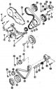
Timing Belt and Engine Covers — Removal and Installation
Diesel toothed belt 1, 4, 5, 7, 8, 9,12, 13, 15, 17, 23, 30, 39. Bolts; 2. Washer; 3. Calmator; 6. Top cover; 10. Bottom cover; 11. Plug; 14. Belt; 16. Washer; 18....
Diesel toothed belt 1, 4, 5, 7, 8, 9,12, 13, 15, 17, 23, 30, 39. Bolts; 2. Washer; 3. Calmator; 6. Top cover; 10. Bottom cover; 11. Plug; 14. Belt; 16. Washer; 18....
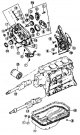
Oil pump and silent rollers (vibration dampers)
Oil pump and vibration damper rollers (diesel) 1. Drain plug; 2, 4, 11. gasket; 3, 6, 7, 9, 16, 17. Bolt; 5. Pallet; 8. Oil receiver; 10. Upper front cover; 12. Seal;...
Oil pump and vibration damper rollers (diesel) 1. Drain plug; 2, 4, 11. gasket; 3, 6, 7, 9, 16, 17. Bolt; 5. Pallet; 8. Oil receiver; 10. Upper front cover; 12. Seal;...
Camshafts and bearings — removal and installation
See also Camshafts and bearings for petrol engines . Removal 1. Disconnect the battery from ground. 2. Remove the cylinder head cover and upper belt cover. 3. Set the...
See also Camshafts and bearings for petrol engines . Removal 1. Disconnect the battery from ground. 2. Remove the cylinder head cover and upper belt cover. 3. Set the...

Removal and installation of a diesel engine
Location of engine number on diesel engine 1. Engine type 2. Serial number Removal and installation of a diesel engine with transmission 1. Hood; 2. Throttle control...
Location of engine number on diesel engine 1. Engine type 2. Serial number Removal and installation of a diesel engine with transmission 1. Hood; 2. Throttle control...

Disassembling a diesel engine
Display of valve timing marks on a diesel engine 1. Timing belt tension roller; 2. Mounting bolts; 3. Mark on the camshaft; 4. Mark on the toothed pulley of the...
Display of valve timing marks on a diesel engine 1. Timing belt tension roller; 2. Mounting bolts; 3. Mark on the camshaft; 4. Mark on the toothed pulley of the...

Pistons and connecting rods — disassembly and inspection
The piston pins are secured on both sides with retaining rings. If it is necessary to replace parts, remove only the pistons from the connecting rods. Disassembly 1. The...
The piston pins are secured on both sides with retaining rings. If it is necessary to replace parts, remove only the pistons from the connecting rods. Disassembly 1. The...

Valves and rocker shafts — disassembly
Valve parts and cylinder head 1. Valve crackers; 2. Valve spring cup; 3. Valve spring; 4. Valve spring support; 5. Valve; 6. Oil deflector cap; 7. Valve seat ring; 8....
Valve parts and cylinder head 1. Valve crackers; 2. Valve spring cup; 3. Valve spring; 4. Valve spring support; 5. Valve; 6. Oil deflector cap; 7. Valve seat ring; 8....

Cylinder head and valves, rocker shafts and rocker arms
Correct assembly of the rocker shaft 1. Intake valve rocker arms; 2. Exhaust valve rocker arms Each of the springs (3) is located between the rocker arms. Assembly...
Correct assembly of the rocker shaft 1. Intake valve rocker arms; 2. Exhaust valve rocker arms Each of the springs (3) is located between the rocker arms. Assembly...

Cylinder head — inspection, assembly and installation
Examination 1. Carefully clean the cylinder head surface from any remaining sealant and check for distortion of its surface adjacent to the cylinder block. To do this,...
Examination 1. Carefully clean the cylinder head surface from any remaining sealant and check for distortion of its surface adjacent to the cylinder block. To do this,...
Checking the compression in the cylinders
A decrease in compression can be the result of a valve not closing, a broken or worn piston ring, or other damage in the cylinder. To determine which cylinder is the...
A decrease in compression can be the result of a valve not closing, a broken or worn piston ring, or other damage in the cylinder. To determine which cylinder is the...

Camshaft and gas distribution mechanism
Measuring the diameter of the camshaft bearing holes Bearing caps must be secured. Examination 1. Install the camshaft in the centers of a lathe or place the bearing...
Measuring the diameter of the camshaft bearing holes Bearing caps must be secured. Examination 1. Install the camshaft in the centers of a lathe or place the bearing...

Timing drive mechanism
Camshaft and high pressure fuel pump drive parts 1. Crankshaft timing belt pulley bolt; 2. Special washer; 3. Crankshaft belt pulley; 4. Upper toothed belt guard; 5....
Camshaft and high pressure fuel pump drive parts 1. Crankshaft timing belt pulley bolt; 2. Special washer; 3. Crankshaft belt pulley; 4. Upper toothed belt guard; 5....

Adjusting valve clearances
Position of the mark on the toothed pulley of the camshaft The mark is indicated by an arrow. Adjusting valve clearances on a diesel engine 1. Open-end wrench 2....
Position of the mark on the toothed pulley of the camshaft The mark is indicated by an arrow. Adjusting valve clearances on a diesel engine 1. Open-end wrench 2....

Adjusting the timing belt tension
Checking the tension of the toothed belt on a diesel engine The belt deflection should be 4–5 mm. 1. Loosen the bolts securing the upper timing belt guard and remove the...
Checking the tension of the toothed belt on a diesel engine The belt deflection should be 4–5 mm. 1. Loosen the bolts securing the upper timing belt guard and remove the...
Removal the lower timing belt guard
1. Remove the upper timing belt guard (four bolts). 2. Loosen the power steering pump drive V-belt and remove the V-belt. 3. Loosen the alternator drive V-belt and...
1. Remove the upper timing belt guard (four bolts). 2. Loosen the power steering pump drive V-belt and remove the V-belt. 3. Loosen the alternator drive V-belt and...
This section is available on: russian, bulgarian, belarusian, ukrainian, serbian, croatian, romanian, polish, slovak, hungarian
Similar materials for other Mitsubishi models
➤ Power unit: Engine repair (diesel) Mitsubishi Colt 4 and 5 (1991-2003)
➤ Power unit: Diesel engine Mitsubishi L200 4 (2005-2014, diesel)
Link in different formats to this section
TEXTHTMLBB Code
- General information
- User manual
- Troubleshooting
- Maintenance
- Technical specifications
- Power unit
- Engine repair
- Cooling system
- Lubrication system
- Fuel system
- Engine management system
- Intake and exhaust system
- Engine electrical equipment
- Transmission
- Clutch
- Manual gearbox
- Automatic gearbox
- Drive shafts
- Chassis and running gear
- Front suspension
- Rear suspension
- Brake system
- Steering
- Body and interior
- Exterior (external elements)
- Interior (internal elements)
- Doors, locks and windows
- Body dimensions
- Electrical equipment
- Safety system (SRS)
- Air conditioner
- Equipment and devices
- Electrical diagrams
- General information
- User manual
- Seats and seat belts
- Instruments and controls
- Driving and operation
- Maintenance
- Power unit
- Gasoline engines
- Diesel engines
- Ignition system
- Engine electrical equipment
- Cooling and lubrication system
- Power and exhaust system
- Fuel system (gasoline)
- Fuel system (diesel)
- Transmission
- Clutch
- Mechanical gearbox
- Automatic gearbox
- Drive shafts and axles
- Chassis and running gear
- Front suspension
- Rear suspension
- Steering
- Brake system
- Body and interior
- Exterior (external elements)
- Interior (internal elements)
- Doors, locks and windows
- Electrical equipment
- Equipment and devices
- Heater and air conditioner
- Cruise control
- Headlights and lighting
- Electrical circuits