



Location of engine number on diesel engine
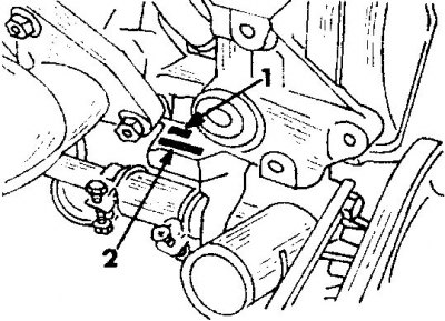
1. Engine type
2. Serial number
Removal and installation of a diesel engine with transmission
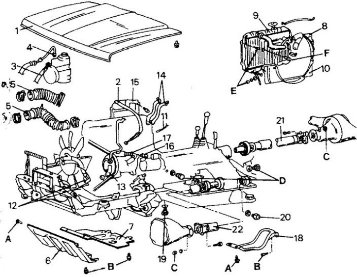
1. Hood; 2. Throttle control cable; 3. Return hose, hydraulic steering system; 4. Pressure hose, hydraulic steering system; 5. Air hose (a) diesel engine, (b) turbodiesel engine; 6. Engine protective tray; 7. Protective tray; 8. Upper radiator trim; 9. Radiator; 10. Lower radiator trim; 11. Cable harness; 12. Oil radiator hoses; 13. Brake booster vacuum hose; 14. Heater hoses; 15. Heat shield; 16. High pressure hose, air conditioner; 17. Low pressure hose, air conditioner; 18. Transfer case protective tray; 19. Transmission oil drain plug; 20. Transfer case oil drain plug; 21. Rear propeller shaft; 22. Front propeller shaft
Key tightening points: A = 18–25 Nm; B = 10–13 Nm; C = 30–35 Nm; D = 30–35 Nm; E = 8–11 Nm; F = 3–5 Nm
The engine is removed together with the gearbox. The figure shows the parts to be removed in the order in which they are to be dismantled. When describing the work, instructions are given only for work operations related to the removal of parts.
1. Open the engine compartment hood. Drain the coolant. The drain plug is located on the bottom of the radiator. The second plug is screwed into the cylinder block.
2. Use a pencil to outline the contours of the engine compartment hood hinges and unscrew the bolts securing the hood to the hinges. Remove the hood with an assistant and set it aside in a protected place.
3. Disconnect and remove the battery.
4. Disconnect the throttle control cable from the high pressure fuel pump.
5. If equipped with power steering, disconnect the return and pressure hoses. Place the hoses in a container provided to drain the liquid.
6. Remove the air hose.
7. Place the front of the vehicle on stands. Remember that the weight of the car is significant, and the stands must be strong enough to support this weight. The soil should be firm enough so that the stands do not sink into the soil. Remove the protective trays from the front of the vehicle.
8. Remove the upper radiator grille, radiator and lower radiator grille.
If equipped with an automatic transmission, disconnect the oil cooler hoses before removing the radiator. If there is an air intake radiator, disconnect its supply lines. Place a container under the transmission to catch any leaking fluid.
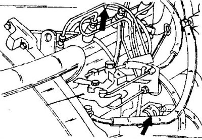
9. Disconnect the cable harness from the engine.
Disconnect all other cables from the engine as follows: On the left side of the engine, disconnect the engine ground cable and the starter cable; disconnect the wires from the high pressure fuel pump (indicated by the arrow) and glow plugs (connectors are indicated by an arrow).
10. If an air conditioner is installed, disconnect the temperature switch cable (near the drain plug) and disconnect the electromagnetic clutch connector.
11. On the right side of the engine, disconnect the alternator wiring harness. Disconnect the ground wire from the bottom of the filter and from the oil pressure switch and oil pressure gauge sensors.
12. Disconnect the oil cooler hoses. The oil should be drained first.
To prevent oil from entering, close the disconnected hoses and openings in the engine with appropriate plugs.
13. Disconnect the vacuum hose from the brake booster.
14. Disconnect the heater hoses from the connection points on the engine compartment bulkhead.
15. Unscrew the protective tray of the transfer case from under the vehicle. Place one container under the gearbox and the other under the transfer case and remove both oil drain plugs. Drain the oil completely and reinstall the plugs. Tightening torque of plugs from 30 to 35 Nm.
16. Unscrew the flange fastenings of the rear and front propeller shafts.
17. If the engine is equipped with a cable winch, remove the drive shaft, cotter pin and shift cable.
18. Unscrew the front muffler pipe flange from the exhaust manifold.
19. Disconnect the speedometer flexible shaft, reverse light switch wires and all-wheel drive indicator light wire harness.
20. Unscrew the clutch slave cylinder from the gearbox side without disconnecting the hoses. Secure the cylinder with wire to the underside of the vehicle, being careful not to put tension on the hose.
21. Remove the engine cross member. First remove the engine mount bolts, then remove the lower cross member mounting bolts. In this case, it is necessary to properly support the engine and gearbox, otherwise the rear side will drop after releasing the cross beam. Turn away the plate.
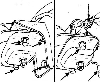
22. Raise the gearbox and transfer case with a roller jack and remove the suspension bracket and transfer case rubber support. After this, unscrew the side plate. Unscrew the suspension bracket from the transfer case (the arrows indicate the bolts that secure the transfer case suspension bracket).
23. Remove the gearshift lever from the gearbox.
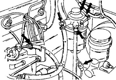
24. Remove the fuel hoses and fuel filter (the arrows indicate the connections on the fuel filter). Open the fuel tank cap to relieve pressure in the fuel tank. To prevent dirt from getting in, insert screws of the appropriate diameter or suitable plugs into the hoses.
Disconnect the condensation indicator wire connector.
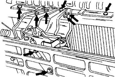
25. Unscrew the bolts (indicated by arrows). This releases the engine compartment hood locking hook and connecting plate (indicated by the arrow)
26. Attach the engine and gearbox to a pulley block or crane using cable loops and chains. Be aware of the weight of the engine. Position the cable or chain loops on the engine so that the engine is tilted with the front side up and the gearbox is hanging down.
The article is based on data from the website: www.MitsubishiMan.ru
27. Raise the power unit enough to relieve the engine mounts and loosen the bolts. Remove the engine mounts from the suspension brackets.
28. Slowly pull the power unit out of the engine compartment. Always be careful not to snag any wires, hoses or tubes, or to detect any loose connections. If the gearbox is stuck in the tie rods, the gearbox should be guided from the bottom of the car over the tie rods.
29. After removing the power unit, the gearbox can be separated from the engine. To do this, remove the starter and unscrew the bolts connecting the gearbox to the engine. Move the gearbox away from the engine in a horizontal position, without loading the weight of the gearbox on its input shaft, as it may be damaged or bent by the driven clutch disc.
30. Before installing the engine and gearbox, check all engine mounts.
Rubber bearings with cracks or other damage must be replaced. The same applies to soft engine mounts.
31. Check fuel, heater and water hoses for damage, cracks or tears. In most cases, damage is observed in areas under the mounting clamps, which are often very poorly visible, even when the clamp is removed.
32. Check fuel, heater and water hoses for damage, cracks or tears. In most cases, damage is observed in areas under the mounting clamps, which are often very poorly visible, even when the clamp is removed.
33. The engine is installed in the reverse order.
34. When installing, connect the engine and gearbox with bolts and install the starter. And here remember that you cannot load the primary shaft with the weight of the gearbox when connecting the gearbox. Tighten the bolts to the specified tightening torque.
35. Lower the engine and gearbox into the engine compartment, install the engine mounts and lower the weight of the power unit onto the engine mounts. Tighten the bolts to the specified tightening torque.
36. Connect the front and rear propeller shafts.
37. Fill the gearbox and transfer case with the prescribed amount of oil. Filling capacities are given in the tables of adjustments and dimensions. It should be taken into account that if a winch is present, more oil must be poured into the transfer case.
38. Connect the air conditioner hoses. After completing the work, the air conditioner should be pressurized.
39. Install the radiator and fill with coolant.
40. Connect the pressure and return hoses of the hydraulic steering system and bleed air from the system.
41. Connect and adjust the throttle cable.
42. Place the hood in the engine compartment, aligning the hinges with the marks made with a pencil during removal, and tighten the hinge bolts. Check how the engine compartment hood closes.
43. When connecting the front muffler pipe to the exhaust manifold, replace the gasket.
44. After installing the engine, fill it with the prescribed amount of oil.
Start the engine and check for coolant, fuel and oil leaks.