



Share with friends:
Electrical equipment and devices Mitsubishi Pajero 4

Special tools
Tool Number and name MB990784 Trim Remover M.U.T.-III MB992006 Sampler MB991223 Test Wiring MB991658 Test Wiring MB991529 Test Wiring
Tool Number and name MB990784 Trim Remover M.U.T.-III MB992006 Sampler MB991223 Test Wiring MB991658 Test Wiring MB991529 Test Wiring

Pre-maintenance inspection
1. Check the corresponding fuses and relays. 2. Check the battery for damage and charge level, check the surface cleanliness and reliability of the wire connections....
1. Check the corresponding fuses and relays. 2. Check the battery for damage and charge level, check the surface cleanliness and reliability of the wire connections....

Checking the level and density of electrolyte
1. Check whether the electrolyte level in the battery is between the UPPER LEVEL marks (Upper level) and LOWER LEVEL (Lower level). 2. Use a hydrometer and thermometer...
1. Check whether the electrolyte level in the battery is between the UPPER LEVEL marks (Upper level) and LOWER LEVEL (Lower level). 2. Use a hydrometer and thermometer...
Charging the battery
1. If the battery is charged from an external source directly on the vehicle, disconnect the vehicle's electrical cables from the battery to prevent damage to electrical...
1. If the battery is charged from an external source directly on the vehicle, disconnect the vehicle's electrical cables from the battery to prevent damage to electrical...

Battery assembly
Removal the battery assembly 1. Disconnect the negative battery terminal wiring connection (1). 2. Disconnect the positive battery terminal wiring connection (models...
Removal the battery assembly 1. Disconnect the negative battery terminal wiring connection (1). 2. Disconnect the positive battery terminal wiring connection (models...

Additional battery pack
Removal the auxiliary battery 1. Disconnect the negative battery terminal wiring connection (1). 2. Disconnect the positive battery terminal wiring connection (2). 3....
Removal the auxiliary battery 1. Disconnect the negative battery terminal wiring connection (1). 2. Disconnect the positive battery terminal wiring connection (2). 3....

Checking the speedometer
1. Adjust the air pressure in the tires to the nominal value. 2. Place the car on chocks and place chocks under the rear wheels. 3. To prevent the front wheels from...
1. Adjust the air pressure in the tires to the nominal value. 2. Place the car on chocks and place chocks under the rear wheels. 3. To prevent the front wheels from...
Checking the tachometer
1. Insert a paper clip into the engine speed sensor connector on the wiring harness side, and connect an external high-precision tachometer. Note: To check the...
1. Insert a paper clip into the engine speed sensor connector on the wiring harness side, and connect an external high-precision tachometer. Note: To check the...
Checking the engine coolant temperature sensor
1. Drain the coolant. 2. Remove the coolant temperature sensor. 3. Immerse the sensor in water at 70°C and measure the resistance. Nominal value: 104±13.5 Ohm. 4. After...
1. Drain the coolant. 2. Remove the coolant temperature sensor. 3. Immerse the sensor in water at 70°C and measure the resistance. Nominal value: 104±13.5 Ohm. 4. After...
Checking the seat belt unfastened indicator on the combined instrument cluster
1. Turn the ignition key to the 'ON' position, unfasten the driver's seat belt and check if the indicator lights up. 2. Turn the ignition key to the 'ON' position,...
1. Turn the ignition key to the 'ON' position, unfasten the driver's seat belt and check if the indicator lights up. 2. Turn the ignition key to the 'ON' position,...
Checking the low engine oil pressure warning light on the instrument cluster
Disconnect the oil pressure switch cable bus connector, turn the ignition key to the 'ON' position, short-circuit the oil pressure switch cable bus connector contact to...
Disconnect the oil pressure switch cable bus connector, turn the ignition key to the 'ON' position, short-circuit the oil pressure switch cable bus connector contact to...
Checking the low engine oil pressure warning light switch on the instrument cluster
Disconnect the engine oil pressure sensor cable bus connector, check the conductivity between the contacts of the low engine oil pressure indicator switch connector and...
Disconnect the engine oil pressure sensor cable bus connector, check the conductivity between the contacts of the low engine oil pressure indicator switch connector and...
Checking the brake warning light on the combination instrument cluster
1. Checking the parking brake indicator: disconnect the wire connector of the parking brake indicator switch, connect the contact of the wire connector of the parking...
1. Checking the parking brake indicator: disconnect the wire connector of the parking brake indicator switch, connect the contact of the wire connector of the parking...
Checking the brake fluid level warning light
Remove the brake fluid reservoir cover and filter, disconnect the brake fluid level indicator wire connector, check the conductivity between the indicator connector...
Remove the brake fluid reservoir cover and filter, disconnect the brake fluid level indicator wire connector, check the conductivity between the indicator connector...
Combined Instrument Cluster Failure Diagnostic Table
Signs Reasons 1. The combined instrument cluster does not work 1. The fuse has blown. 2. The cable bus or connectors are damaged. 3. Malfunction in the combined...
Signs Reasons 1. The combined instrument cluster does not work 1. The fuse has blown. 2. The cable bus or connectors are damaged. 3. Malfunction in the combined...

Instrument cluster assembly
Removal the instrument cluster assembly Attention: Be careful not to damage the instruments or instrument panel. Be careful not to damage the instrument cluster glass....
Removal the instrument cluster assembly Attention: Be careful not to damage the instruments or instrument panel. Be careful not to damage the instrument cluster glass....
Headlight adjustment
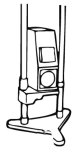
Using headlight beam adjustment equipment 1. Headlamps must be adjusted on proper equipment in accordance with the equipment manufacturer's instructions. Note: If there...
Using headlight beam adjustment equipment 1. Headlamps must be adjusted on proper equipment in accordance with the equipment manufacturer's instructions. Note: If there...
Measuring the brightness of headlights
Using a photometer and following the manufacturer's instructions, measure the brightness of the headlights. Limit value: 30,000 cd or more. Note: When measuring the...
Using a photometer and following the manufacturer's instructions, measure the brightness of the headlights. Limit value: 30,000 cd or more. Note: When measuring the...

Adjusting the front fog lights
1. Determine the position of the center of the fog lights as shown in the figure. 2. Set the distance from the centers of the fog lights to the screen to 3 m, as shown...
1. Determine the position of the center of the fog lights as shown in the figure. 2. Set the distance from the centers of the fog lights to the screen to 3 m, as shown...

Replacing lamps
Headlight low beam lamp Caution: Do not touch the surface of the lamp with your hands or dirty cloth. If its surface gets dirty, clean it with alcohol or solvent and let...
Headlight low beam lamp Caution: Do not touch the surface of the lamp with your hands or dirty cloth. If its surface gets dirty, clean it with alcohol or solvent and let...

Removal the headlight
Note: The removal procedure is the same for both left and right side headlights. 1. Remove the front bumper assembly. 2. Remove the headlamp assembly (1). 3. Remove the...
Note: The removal procedure is the same for both left and right side headlights. 1. Remove the front bumper assembly. 2. Remove the headlamp assembly (1). 3. Remove the...
Installing headlights
Note: The installation procedure is the same for both left and right side headlights. Note: When installing, tighten the bolts to the tightening torques shown in the...
Note: The installation procedure is the same for both left and right side headlights. Note: When installing, tighten the bolts to the tightening torques shown in the...

Headlamp level adjustment switch
Removal the headlight leveling switch Left hand drive model Right hand drive model 1. Remove the lower panel assembly (1). 2. Remove the headlight level adjustment...
Removal the headlight leveling switch Left hand drive model Right hand drive model 1. Remove the lower panel assembly (1). 2. Remove the headlight level adjustment...

Automatic headlight adjustment control unit for main lighting
Removal the automatic headlight adjustment control unit 1. Remove the front side panel. 2. Remove the main lighting headlight automatic adjustment control unit (1). 1)...
Removal the automatic headlight adjustment control unit 1. Remove the front side panel. 2. Remove the main lighting headlight automatic adjustment control unit (1). 1)...
Installation of the automatic headlight adjustment control unit
1. Install the automatic headlight adjustment control unit (1). 2. Install the front side panel.
1. Install the automatic headlight adjustment control unit (1). 2. Install the front side panel.

Front fog lights
Removal the front fog lights Note: The removal procedure is the same for both left and right side headlights. 1. Remove the front fog light (1). 1) Remove the clamps and...
Removal the front fog lights Note: The removal procedure is the same for both left and right side headlights. 1. Remove the front fog light (1). 1) Remove the clamps and...

Rear fog lights
Removal the rear fog lights 1. Remove the rear fog light assembly (1). 2. Remove the cartridge (2). 3. Remove the light bulb (3). Installing rear fog lights Note: When...
Removal the rear fog lights 1. Remove the rear fog light assembly (1). 2. Remove the cartridge (2). 3. Remove the light bulb (3). Installing rear fog lights Note: When...

Rear fog light switch
Removal the rear fog light switch Left hand drive model Right hand drive model 1. Remove the lower panel assembly (1). 2. Remove the rear fog light switch (2)....
Removal the rear fog light switch Left hand drive model Right hand drive model 1. Remove the lower panel assembly (1). 2. Remove the rear fog light switch (2)....

Side turn signal repeater
Removal the side turn signal repeater 1. Remove the mirror (1). 2. Remove the housing cover (2). 3. Remove the side turn signal repeater (3). 4. Remove the light bulb...
Removal the side turn signal repeater 1. Remove the mirror (1). 2. Remove the housing cover (2). 3. Remove the side turn signal repeater (3). 4. Remove the light bulb...

Rear combination light
Removal the rear combination light 1. Remove the rear combination light assembly (1). 2. Remove the rear combination light module (2). 3. Remove the cartridge (3). 4....
Removal the rear combination light 1. Remove the rear combination light assembly (1). 2. Remove the rear combination light module (2). 3. Remove the cartridge (3). 4....

Additional brake light
Removal an additional brake light 1. Remove the upper trim of the trunk door. 2. Remove the additional brake light assembly (1). 3. Remove the cartridge (2). 4. Remove...
Removal an additional brake light 1. Remove the upper trim of the trunk door. 2. Remove the additional brake light assembly (1). 3. Remove the cartridge (2). 4. Remove...

License plate light
Removal the license plate light 1. Remove the license plate light assembly (1). 2. Remove the cartridge (2). 3. Remove the light bulb (3). Installing a license plate...
Removal the license plate light 1. Remove the license plate light assembly (1). 2. Remove the cartridge (2). 3. Remove the light bulb (3). Installing a license plate...

Front interior lighting lamp
Removal the front interior light bulb 1. Remove the lenses (1). 2. Remove the light bulb (2). 3. Remove the front interior light bulb (3). 4. Remove the bracket (4)....
Removal the front interior light bulb 1. Remove the lenses (1). 2. Remove the light bulb (2). 3. Remove the front interior light bulb (3). 4. Remove the bracket (4)....

Rear personal lamp
Removal the rear headlamp Model without dual air conditioner Model with dual air conditioner 1. Remove the lenses (1). 2. Remove the light bulb (2). 3. Remove the rear...
Removal the rear headlamp Model without dual air conditioner Model with dual air conditioner 1. Remove the lenses (1). 2. Remove the light bulb (2). 3. Remove the rear...

Luggage compartment light
Removal the luggage compartment light 1. Remove the lenses (1). 2. Remove the bulb (2). 3. Remove the clamp (3). 4. Remove the luggage compartment light (4). Installing...
Removal the luggage compartment light 1. Remove the lenses (1). 2. Remove the bulb (2). 3. Remove the clamp (3). 4. Remove the luggage compartment light (4). Installing...
Floor lighting bulbs
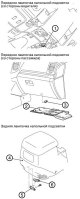
Removal floor lighting bulbs 1. Remove the front floor light bulb (from the driver's side) (1). 2. Remove the lower side cover on the passenger side (2). 3. Remove the...
Removal floor lighting bulbs 1. Remove the front floor light bulb (from the driver's side) (1). 2. Remove the lower side cover on the passenger side (2). 3. Remove the...

Hazard warning light switch
Removal the hazard warning light switch 1. Remove the central air outlet deflector (1). 2. Remove the hazard warning light switch fastening (2). 3. Remove the hazard...
Removal the hazard warning light switch 1. Remove the central air outlet deflector (1). 2. Remove the hazard warning light switch fastening (2). 3. Remove the hazard...

Removal the ETACS electronic control unit
1. Remove the lower instrument panel cover. 2. Remove the fuse box (1). 3. Remove the ETACS electronic control unit (2).
1. Remove the lower instrument panel cover. 2. Remove the fuse box (1). 3. Remove the ETACS electronic control unit (2).
Installation of the ETACS electronic control unit
1. Install the ETACS electronic control unit (2). 2. Install the fuse box (1). 3. Install the lower instrument panel cover.
1. Install the ETACS electronic control unit (2). 2. Install the fuse box (1). 3. Install the lower instrument panel cover.
Signal — Failure Diagnostic Table
Signs Reasons Both sound signals do not work 1. The fuse has blown. 2. Failure of the horn relay. 3. Failure of the sound signal switch. 4. Sound signal failure. 5....
Signs Reasons Both sound signals do not work 1. The fuse has blown. 2. Failure of the horn relay. 3. Failure of the sound signal switch. 4. Sound signal failure. 5....

Removal the signal
1. Remove the front bumper grille. 2. Remove the signal (high) (1). 3. Remove the signal (low) (2).
1. Remove the front bumper grille. 2. Remove the signal (high) (1). 3. Remove the signal (low) (2).
Setting the signal
Note: When installing, tighten the bolts to the tightening torques shown in the figure. 1. Set signal (low) (2). 2. Set the signal (high) (1). 3. Install the front...
Note: When installing, tighten the bolts to the tightening torques shown in the figure. 1. Set signal (low) (2). 2. Set the signal (high) (1). 3. Install the front...

Removal the ignition switch
Caution: Before removing the air bag module and clock spring, refer to Chapter - Safety Precautions for Servicing the SRS System, Air Bag Module, and Clock Spring. 1....
Caution: Before removing the air bag module and clock spring, refer to Chapter - Safety Precautions for Servicing the SRS System, Air Bag Module, and Clock Spring. 1....
Installing the ignition switch
Note: When installing, tighten the bolts to the tightening torques shown in the figure. 1. Install the steering column lock cylinder (5). 2. Install the immobilizer...
Note: When installing, tighten the bolts to the tightening torques shown in the figure. 1. Install the steering column lock cylinder (5). 2. Install the immobilizer...
Rear window heating device
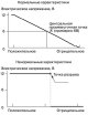
Checking and repairing without dismantling from the vehicle 1. Start the engine, adjust the speed to approximately 2000 rpm. Check the rear window defroster elements...
Checking and repairing without dismantling from the vehicle 1. Start the engine, adjust the speed to approximately 2000 rpm. Check the rear window defroster elements...
Immobilizer system — identification code registration method
After purchasing a new ignition key or replacing the immobilizer electronic control unit, you must register the identification codes for each new key in the immobilizer...
After purchasing a new ignition key or replacing the immobilizer electronic control unit, you must register the identification codes for each new key in the immobilizer...

Immobilizer control module
Removal the immobilizer control module Model with 3200 cc engine 1. Remove the lower instrument panel cover. 2. Remove the immobilizer control module wiring (1). 3....
Removal the immobilizer control module Model with 3200 cc engine 1. Remove the lower instrument panel cover. 2. Remove the immobilizer control module wiring (1). 3....

Remote control for closing/opening doors
Disassembling the remote control for closing/opening doors 1. Remove the screw (1). 2. Remove the top cover (2). 3. Remove the repeater (3). 4. Remove the transmitter...
Disassembling the remote control for closing/opening doors 1. Remove the screw (1). 2. Remove the top cover (2). 3. Remove the repeater (3). 4. Remove the transmitter...
Audio and navigation system
Audio and Navigation System Failure Diagnostic Chart Signs Reasons The audio system does not turn on after pressing the power switch button 1. Failure in the audio...
Audio and Navigation System Failure Diagnostic Chart Signs Reasons The audio system does not turn on after pressing the power switch button 1. Failure in the audio...

Rear view camera
Removal the rear view camera 1. Remove the rear view camera (1). 2. Remove the screw washer (2). Installing a rear view camera 1. Install the screw washer (2). 2....
Removal the rear view camera 1. Remove the rear view camera (1). 2. Remove the screw washer (2). Installing a rear view camera 1. Install the screw washer (2). 2....

Radio and CD player
Removal the radio and CD player 1. Remove the lower center panel assembly (1). 2. Remove the central air outlet deflector (2). 3. Remove the upper center panel assembly...
Removal the radio and CD player 1. Remove the lower center panel assembly (1). 2. Remove the central air outlet deflector (2). 3. Remove the upper center panel assembly...

Navigation system
Removal the navigation system 1. Remove the center lower panel assembly (1). 2. Remove the central air outlet deflector (2). 3. Remove the center top panel assembly (3)....
Removal the navigation system 1. Remove the center lower panel assembly (1). 2. Remove the central air outlet deflector (2). 3. Remove the center top panel assembly (3)....

Sound amplifier
Removal the audio amplifier 1. Remove the left rear trim. 2. Remove the rear speaker assembly. 3. Remove the audio amplifier (1). 4. Remove the rear audio amplifier...
Removal the audio amplifier 1. Remove the left rear trim. 2. Remove the rear speaker assembly. 3. Remove the audio amplifier (1). 4. Remove the rear audio amplifier...

Built-in audio control switch
Caution: Before removing the air bag module and clock spring, refer to Chapter - Safety Precautions When Servicing the SRS, Air Bag Module, and Clock Spring . Removal...
Caution: Before removing the air bag module and clock spring, refer to Chapter - Safety Precautions When Servicing the SRS, Air Bag Module, and Clock Spring . Removal...

Speakers — Removal
Removal the speakers Front or rear door speaker 1. Remove the front door trim. 2. Remove the screws (2). 3. Remove the front door speaker (1). 4. Remove the rear door...
Removal the speakers Front or rear door speaker 1. Remove the front door trim. 2. Remove the screws (2). 3. Remove the front door speaker (1). 4. Remove the rear door...
Speakers — Installation
Installing speakers Front or rear door speaker 1. Install the rear door speaker bracket (5). 2. Tighten the screws (6). 3. Install the rear door speaker (3). 4. Tighten...
Installing speakers Front or rear door speaker 1. Install the rear door speaker bracket (5). 2. Tighten the screws (6). 3. Install the rear door speaker (3). 4. Tighten...

Rear display
Removal the rear display 1. Remove the rear display bezel (1). 2. Remove the rear monitor (2). 3. Remove the bracket (3). 4. Remove the audio and video adapter (4)....
Removal the rear display 1. Remove the rear display bezel (1). 2. Remove the rear monitor (2). 3. Remove the bracket (3). 4. Remove the audio and video adapter (4)....

Central display
Removal the central display 1. Remove the upper trim of the luggage compartment door. 2. Remove the compass sensor (1). 1) Press the compass sensor in the direction...
Removal the central display 1. Remove the upper trim of the luggage compartment door. 2. Remove the compass sensor (1). 1) Press the compass sensor in the direction...
Windows with glass servo drive
Power Window Failure Diagnostic Table Signs Reasons All the windows don't work (the central door locking device also does not work) 1. The fuse for the power supply...
Power Window Failure Diagnostic Table Signs Reasons All the windows don't work (the central door locking device also does not work) 1. The fuse for the power supply...

Checking the window lifter safety mechanism
1. Place a wooden block of about 10mm thickness as shown in the figure, and then lift the door glass. 2. Check that when the block is clamped, the glass drops to a...
1. Place a wooden block of about 10mm thickness as shown in the figure, and then lift the door glass. 2. Check that when the block is clamped, the glass drops to a...

Checking the current in the window lifter drive circuit
1. Remove the power window circuit fuse and connect the tester as shown in the figure. 2. When the window switch is pressed to the "UP" position, the maximum current...
1. Remove the power window circuit fuse and connect the tester as shown in the figure. 2. When the window switch is pressed to the "UP" position, the maximum current...

Checking the circuit breaker (built into the window lift motor)
1. Press the window switch to the "UP" position, close the window completely, and continue to hold the switch in this position for 10 seconds. 2. Release the switch and...
1. Press the window switch to the "UP" position, close the window completely, and continue to hold the switch in this position for 10 seconds. 2. Release the switch and...
Power window switch
Removal the window switch 1. Remove the window lift switch using the special tool MB990784. 2. Disconnect the window switch connectors. Installing the window lift switch...
Removal the window switch 1. Remove the window lift switch using the special tool MB990784. 2. Disconnect the window switch connectors. Installing the window lift switch...
Window lift motor
Note: The operations for removing and installing the window lift motor are described in Chapter 19 - "Body" .
Note: The operations for removing and installing the window lift motor are described in Chapter 19 - "Body" .
Windscreen wipers and washer
Windshield Wiper and Washer System Failure Diagnostic Chart Signs Reasons Windscreen wipers and washer do not work 1. Ignition relay No. 1 failure. 2. The windshield...
Windshield Wiper and Washer System Failure Diagnostic Chart Signs Reasons Windscreen wipers and washer do not work 1. Ignition relay No. 1 failure. 2. The windshield...

Front windshield wiper
Removal the front windshield wiper 1. Remove the wiper blade assembly (1). 2. Remove the wiper blade (2). 3. Remove the wiper arm and blade assembly (3). 4. Remove the...
Removal the front windshield wiper 1. Remove the wiper blade assembly (1). 2. Remove the wiper blade (2). 3. Remove the wiper arm and blade assembly (3). 4. Remove the...

Front windshield washer
Removal the front windshield washer 1. Remove the hood insulation. 2. Remove the front windshield washer nozzle (1). 3. Remove the front windshield washer hose (2). 4....
Removal the front windshield washer 1. Remove the hood insulation. 2. Remove the front windshield washer nozzle (1). 3. Remove the front windshield washer hose (2). 4....

Rear windshield wiper and washer
Removal the rear windshield wiper and washer 1. Remove the rear wiper blade assembly (1). 2. Remove the rear wiper blade (2). 3. Remove the luggage compartment door...
Removal the rear windshield wiper and washer 1. Remove the rear wiper blade assembly (1). 2. Remove the rear wiper blade (2). 3. Remove the luggage compartment door...

Headlight washer for head lighting
Removal the headlight washer 1. Remove the front right wheel. 2. Remove the right mudguard. 3. Disconnect the headlight washer hose connection (from the bumper side)...
Removal the headlight washer 1. Remove the front right wheel. 2. Remove the right mudguard. 3. Disconnect the headlight washer hose connection (from the bumper side)...
This section is available on: russian, bulgarian, belarusian, ukrainian, serbian, croatian, romanian, polish, slovak, hungarian
Similar materials for other Mitsubishi models
➤ Electrical equipment: Equipment and devices Mitsubishi Colt 4 and 5 (1991-2003)
➤ Electrical equipment: Equipment and devices Mitsubishi Lancer 3 and 5 (1984-1992)
➤ Electrical equipment: Equipment and devices Mitsubishi Galant 5 (1983-1989, petrol)
➤ Electrical equipment: Equipment and devices Mitsubishi L200 4 (2005-2014, diesel)
➤ General information: Salon equipment Mitsubishi Outlander 1 (2003-2008)
➤ Electrical equipment: Equipment and devices Mitsubishi Carisma (1995-2004)
Link in different formats to this section
TEXTHTMLBB Code
- General information
- User manual
- Troubleshooting
- Maintenance
- Technical specifications
- Power unit
- Engine repair
- Cooling system
- Lubrication system
- Fuel system
- Engine management system
- Intake and exhaust system
- Engine electrical equipment
- Transmission
- Clutch
- Manual gearbox
- Automatic gearbox
- Drive shafts
- Chassis and running gear
- Front suspension
- Rear suspension
- Brake system
- Steering
- Body and interior
- Exterior (external elements)
- Interior (internal elements)
- Doors, locks and windows
- Body dimensions
- Electrical equipment
- Safety system (SRS)
- Air conditioner
- Equipment and devices
- Electrical diagrams
- General information
- User manual
- Seats and seat belts
- Instruments and controls
- Driving and operation
- Maintenance
- Power unit
- Gasoline engines
- Diesel engines
- Ignition system
- Engine electrical equipment
- Cooling and lubrication system
- Power and exhaust system
- Fuel system (gasoline)
- Fuel system (diesel)
- Transmission
- Clutch
- Mechanical gearbox
- Automatic gearbox
- Drive shafts and axles
- Chassis and running gear
- Front suspension
- Rear suspension
- Steering
- Brake system
- Body and interior
- Exterior (external elements)
- Interior (internal elements)
- Doors, locks and windows
- Electrical equipment
- Equipment and devices
- Heater and air conditioner
- Cruise control
- Headlights and lighting
- Electrical circuits