



Share with friends:
Car engine repair Mitsubishi Pajero 4

Engine Mechanical Part — General Information
Indicators Engine 6V31 Engine 6G7 Engine 4M4 Working volume, cm³ 2998 3828 3200 Cylinder diameter and piston stroke, mm 87.6 x 82.9 95,0 - 90,0 98,5-105 Compression...
Indicators Engine 6V31 Engine 6G7 Engine 4M4 Working volume, cm³ 2998 3828 3200 Cylinder diameter and piston stroke, mm 87.6 x 82.9 95,0 - 90,0 98,5-105 Compression...
Mechanical part of the engine — sealants
Position Sealants Notes Cylinder head cover, cylinder head Semi-circular plug ZM ATD PART 8660 or similar - Oil pan Thermostat housing MD 970389 or equivalent...
Position Sealants Notes Cylinder head cover, cylinder head Semi-circular plug ZM ATD PART 8660 or similar - Oil pan Thermostat housing MD 970389 or equivalent...

Engine Mechanical Part — Equipment and Tools
Drawing Name and code M.U.T.-III MB991800 Pulley Holder MB991802 Crankshaft Pulley Holder Special Bolt MB990767 Fork Holder MD998715 Special bolt MD998713 Camshaft Seal...
Drawing Name and code M.U.T.-III MB991800 Pulley Holder MB991802 Crankshaft Pulley Holder Special Bolt MB990767 Fork Holder MD998715 Special bolt MD998713 Camshaft Seal...

Technical operations on the car — checking the tension of the alternator drive belt
1. Use a special tool to check the belt tension in the middle between the two pulleys as shown in the figure. 2. Press the belt at this point with a force of 98 N,...
1. Use a special tool to check the belt tension in the middle between the two pulleys as shown in the figure. 2. Press the belt at this point with a force of 98 N,...
Checking and adjusting the tension of the power steering pump and air conditioning compressor drive belt
1. Using a special tool, check the belt tension at the point midway between the crankshaft pulley and the power steering pump. 2. Press the belt at this point with a...
1. Using a special tool, check the belt tension at the point midway between the crankshaft pulley and the power steering pump. 2. Press the belt at this point with a...

Checking the ignition timing angle
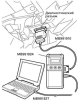
1. Prepare the vehicle for inspection (warm up the engine to normal coolant temperature). 2. Connect the MUT-III device to the diagnostic connector. 3. Install the...
1. Prepare the vehicle for inspection (warm up the engine to normal coolant temperature). 2. Connect the MUT-III device to the diagnostic connector. 3. Install the...
Checking the idle speed
1. Prepare the vehicle for inspection (warm up the engine to normal coolant temperature). 2. Turn off the ignition and connect the MUT-III device to the diagnostic...
1. Prepare the vehicle for inspection (warm up the engine to normal coolant temperature). 2. Turn off the ignition and connect the MUT-III device to the diagnostic...
Checking the air-fuel mixture composition at idle
1. Prepare the vehicle for inspection (warm up the engine to normal coolant temperature). 2. Turn off the ignition and connect the MUT-III device to the diagnostic...
1. Prepare the vehicle for inspection (warm up the engine to normal coolant temperature). 2. Turn off the ignition and connect the MUT-III device to the diagnostic...

Compression check
1. Before starting the test, check the condition of the engine oil, as well as the starter and battery. Prepare the vehicle for inspection (warm up the engine to normal...
1. Before starting the test, check the condition of the engine oil, as well as the starter and battery. Prepare the vehicle for inspection (warm up the engine to normal...

Checking the vacuum in the intake manifold
1. Start the engine and warm it up to a coolant temperature of 80 - 95°C. 2. Connect the tachometer. 3. Connect the tee to the vacuum hose between the fuel pressure...
1. Start the engine and warm it up to a coolant temperature of 80 - 95°C. 2. Connect the tachometer. 3. Connect the tee to the vacuum hose between the fuel pressure...
Checking hydraulic compensators
If after starting the engine an extraneous noise (knocking) from the hydraulic lifters appears and does not disappear as the engine warms up, carry out the following...
If after starting the engine an extraneous noise (knocking) from the hydraulic lifters appears and does not disappear as the engine warms up, carry out the following...
Simple check of hydraulic compensators
1. Stop the engine. 2. Remove the cylinder head cover. 3. Set the piston of cylinder No. 1 to TDC of the compression stroke. 4. Check the rocker arms, indicated by white...
1. Stop the engine. 2. Remove the cylinder head cover. 3. Set the piston of cylinder No. 1 to TDC of the compression stroke. 4. Check the rocker arms, indicated by white...

Removal air from hydraulic compensators
Note: If the vehicle has been parked on a slope for an extended period of time, the amount of oil in the hydraulic lifters will decrease and air may enter the high...
Note: If the vehicle has been parked on a slope for an extended period of time, the amount of oil in the hydraulic lifters will decrease and air may enter the high...

Removal the crankshaft pulley
Model with 6V31 engine 1. Remove the lower side engine protection. 2. Remove the generator drive belt (1). Caution: When reusing the alternator drive belt, mark it with...
Model with 6V31 engine 1. Remove the lower side engine protection. 2. Remove the generator drive belt (1). Caution: When reusing the alternator drive belt, mark it with...

Installing the crankshaft pulley
Model with 6V31 engine Note: When installing, tighten the bolts to the torques shown in the figure. 1. Install the crankshaft pulley (6). 2. Install the crankshaft...
Model with 6V31 engine Note: When installing, tighten the bolts to the torques shown in the figure. 1. Install the crankshaft pulley (6). 2. Install the crankshaft...

Removal the camshaft
Model with 6V31 engine 1. Remove the engine cover. 2. Remove the timing belt. 3. Remove the thermostat housing. 4. Remove the oil dipstick (1). 5. Remove the sealing...
Model with 6V31 engine 1. Remove the engine cover. 2. Remove the timing belt. 3. Remove the thermostat housing. 4. Remove the oil dipstick (1). 5. Remove the sealing...
Installing the camshaft and camshaft seal
Model with 6V31 engine Note: When installing, tighten the bolts to the torques shown in the figure. 1. Install the valve spring seat (27). 2. Install the valve stem seal...
Model with 6V31 engine Note: When installing, tighten the bolts to the torques shown in the figure. 1. Install the valve spring seat (27). 2. Install the valve stem seal...

Removal the oil pan and oil filter
Note: The operations for removing the oil pan and oil filter on a vehicle with a 6V31, 4M4 or 6G7 engine are similar. Below is a description of the procedure using the...
Note: The operations for removing the oil pan and oil filter on a vehicle with a 6V31, 4M4 or 6G7 engine are similar. Below is a description of the procedure using the...
Installing the oil pan and oil filter
Note: The operations for installing the oil pan and oil filter on a vehicle with a 6V31, 4M4 or 6G7 engine are similar. Below is a description of the procedure using the...
Note: The operations for installing the oil pan and oil filter on a vehicle with a 6V31, 4M4 or 6G7 engine are similar. Below is a description of the procedure using the...

Removal the crankshaft seals
Model with 6V31 engine 1. Remove the crankshaft sprocket (1). 2. Remove the cotter pin (2). 3. Remove the front crankshaft oil seal (3). 1. Remove the timing belt. 2....
Model with 6V31 engine 1. Remove the crankshaft sprocket (1). 2. Remove the cotter pin (2). 3. Remove the front crankshaft oil seal (3). 1. Remove the timing belt. 2....

Installing crankshaft seals
Model with 6V31 engine 1. Install the front crankshaft oil seal (3). 1) Apply a small amount of engine oil to the lip of the oil seal. 2) Install the oil seal into the...
Model with 6V31 engine 1. Install the front crankshaft oil seal (3). 1) Apply a small amount of engine oil to the lip of the oil seal. 2) Install the oil seal into the...

Removal the cylinder head gasket
Model with 6V31 engine 1. Remove the intake manifold. 2. Remove the exhaust manifold. 3. Remove the timing belt. 4. Remove the thermostat housing. 5. Remove the...
Model with 6V31 engine 1. Remove the intake manifold. 2. Remove the exhaust manifold. 3. Remove the timing belt. 4. Remove the thermostat housing. 5. Remove the...

Installing the cylinder head gasket
Model with 6V31 engine Note: When installing, tighten the bolts to the torques shown in the figure. 1. Install the cylinder head gasket (26). 2. Install the right...
Model with 6V31 engine Note: When installing, tighten the bolts to the torques shown in the figure. 1. Install the cylinder head gasket (26). 2. Install the right...

Removal the timing belt
Model with 6V31 engine 1. Remove the engine cover. 2. Remove the lower and side engine protection. 3. Remove the timing belt automatic tensioner (1). 4. Remove the...
Model with 6V31 engine 1. Remove the engine cover. 2. Remove the lower and side engine protection. 3. Remove the timing belt automatic tensioner (1). 4. Remove the...

Installing the timing belt
Model with 6V31 engine Note: When installing, tighten the bolts to the torques shown in the figure. 1. Install the tension pulley assembly (13). 2. Install the timing...
Model with 6V31 engine Note: When installing, tighten the bolts to the torques shown in the figure. 1. Install the tension pulley assembly (13). 2. Install the timing...

Adjusting the timing belt tension of the gas distribution mechanism
1. After turning the crankshaft 1/4 turn counterclockwise, turn it clockwise until the timing marks are aligned. 2. Loosen the tensioner pulley fixing bolt, and then use...
1. After turning the crankshaft 1/4 turn counterclockwise, turn it clockwise until the timing marks are aligned. 2. Loosen the tensioner pulley fixing bolt, and then use...

Removal the timing chain
Model with 4M4 engine 1. Remove the main and auxiliary batteries. 2. Remove the lower support plate and engine crankcase guard. 3. Drain the coolant. 4. Drain the oil...
Model with 4M4 engine 1. Remove the main and auxiliary batteries. 2. Remove the lower support plate and engine crankcase guard. 3. Drain the coolant. 4. Drain the oil...
Installing the timing chain
Model with 4M4 engine 1. Install the lower guide plate (16). 2. Install the guide plate (15). 3. Install the tensioner lever shaft assembly (14). 4. Install the...
Model with 4M4 engine 1. Install the lower guide plate (16). 2. Install the guide plate (15). 3. Install the tensioner lever shaft assembly (14). 4. Install the...
Removal the engine assembly
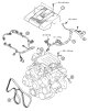
Note: The operations for removing the 6V31, 4M4 or 6G7 engine are similar. Below is a description of the procedure using the 6G7 engine as an example. Note: Use a...
Note: The operations for removing the 6V31, 4M4 or 6G7 engine are similar. Below is a description of the procedure using the 6G7 engine as an example. Note: Use a...
Installing the engine assembly
Note: The installation operations for the 6V31, 4M4 or 6G7 engine are similar. Below is a description of the procedure using the 6G7 engine as an example. 1. Install the...
Note: The installation operations for the 6V31, 4M4 or 6G7 engine are similar. Below is a description of the procedure using the 6G7 engine as an example. 1. Install the...

Checking the camshaft
1. Measure the height of the cams. If the height is less than the minimum permissible value, replace the camshaft (See table and figure). Standard value (mm) Minimum...
1. Measure the height of the cams. If the height is less than the minimum permissible value, replace the camshaft (See table and figure). Standard value (mm) Minimum...

Cylinder head and valves
Cylinder head 1. Before cleaning the cylinder head, check the head for water or air leaks, cracks or other defects. 2. Remove engine oil, adhesive sealant, soot and...
Cylinder head 1. Before cleaning the cylinder head, check the head for water or air leaks, cracks or other defects. 2. Remove engine oil, adhesive sealant, soot and...

Oil pump and oil pan
Oil pump 1. Insert the rotor into the front part of the housing. 2. Measure the radial clearance as shown in the figure. Standard value: 0.06-0.18 mm. 3. Measure the...
Oil pump 1. Insert the rotor into the front part of the housing. 2. Measure the radial clearance as shown in the figure. Standard value: 0.06-0.18 mm. 3. Measure the...

Removal pistons and connecting rods
1. Unscrew the connecting rod cap nut (1). 2. Remove the connecting rod cover (2). 1) Mark the cylinder number on the side of the connecting rod before dismantling, as...
1. Unscrew the connecting rod cap nut (1). 2. Remove the connecting rod cover (2). 1) Mark the cylinder number on the side of the connecting rod before dismantling, as...

Installing pistons and connecting rods
1. Tighten the bolt (14). 2. Install the connecting rod (13). 3. Install the piston (12). 4. Install the spring ring (11). 5. Install the piston pin (10). 6. Install the...
1. Tighten the bolt (14). 2. Install the connecting rod (13). 3. Install the piston (12). 4. Install the spring ring (11). 5. Install the piston pin (10). 6. Install the...

Checking pistons and connecting rods
Piston ring 1. Check the piston ring axial clearance. If it exceeds the maximum allowable value, replace the piston ring, piston, or both (See the picture). Standard...
Piston ring 1. Check the piston ring axial clearance. If it exceeds the maximum allowable value, replace the piston ring, piston, or both (See the picture). Standard...

Removal the crankshaft and cylinder block
Model with 6V31 engine 1. Unscrew the flywheel bolt (1).; 2. Remove the adapter plate (2).; 3. Remove the flywheel (3).; 4. Remove the back plate (4).; 5. Remove the...
Model with 6V31 engine 1. Unscrew the flywheel bolt (1).; 2. Remove the adapter plate (2).; 3. Remove the flywheel (3).; 4. Remove the back plate (4).; 5. Remove the...
Installing the crankshaft and cylinder block
Model with 6V31 engine Note: When installing, tighten the bolts to the torques shown in the figure. 1. Install the cylinder block (18). 2. Install the stiffener gasket...
Model with 6V31 engine Note: When installing, tighten the bolts to the torques shown in the figure. 1. Install the cylinder block (18). 2. Install the stiffener gasket...

Checking the crankshaft and cylinder block
Radial clearance of crankshaft journal The radial clearance of the crankshaft journal can be conveniently measured using a plastic template. Measurement procedure: 1....
Radial clearance of crankshaft journal The radial clearance of the crankshaft journal can be conveniently measured using a plastic template. Measurement procedure: 1....
This section is available on: russian, bulgarian, belarusian, ukrainian, serbian, croatian, romanian, polish, slovak, hungarian
Similar materials for other Mitsubishi models
➤ Power unit: Engine in a car Mitsubishi Colt 2 and 3 (1983-1993)
➤ Power unit: Repair of GDI engines Mitsubishi Lancer 9 (2000-2007, petrol)
➤ Power unit: Engine repair Mitsubishi Galant 5 (1983-1989, petrol)
➤ Power unit: Engine repair Mitsubishi Outlander 1 (2003-2008)
Link in different formats to this section
TEXTHTMLBB Code
- General information
- User manual
- Troubleshooting
- Maintenance
- Technical specifications
- Power unit
- Engine repair
- Cooling system
- Lubrication system
- Fuel system
- Engine management system
- Intake and exhaust system
- Engine electrical equipment
- Transmission
- Clutch
- Manual gearbox
- Automatic gearbox
- Drive shafts
- Chassis and running gear
- Front suspension
- Rear suspension
- Brake system
- Steering
- Body and interior
- Exterior (external elements)
- Interior (internal elements)
- Doors, locks and windows
- Body dimensions
- Electrical equipment
- Safety system (SRS)
- Air conditioner
- Equipment and devices
- Electrical diagrams
- General information
- User manual
- Seats and seat belts
- Instruments and controls
- Driving and operation
- Maintenance
- Power unit
- Gasoline engines
- Diesel engines
- Ignition system
- Engine electrical equipment
- Cooling and lubrication system
- Power and exhaust system
- Fuel system (gasoline)
- Fuel system (diesel)
- Transmission
- Clutch
- Mechanical gearbox
- Automatic gearbox
- Drive shafts and axles
- Chassis and running gear
- Front suspension
- Rear suspension
- Steering
- Brake system
- Body and interior
- Exterior (external elements)
- Interior (internal elements)
- Doors, locks and windows
- Electrical equipment
- Equipment and devices
- Heater and air conditioner
- Cruise control
- Headlights and lighting
- Electrical circuits