
English Русский
Български
Беларускі
Український
Српски
Hrvatski
Română
Polski
Slovenský
Magyar
Articles Bookmark Contacts Sitemap   
Company Audi Company Ford Company Hyundai Company Kia Company Mazda Company Mercedes-Benz Company Nissan
MitsubishiMan.ru


Home Colt Lancer Galant L200 Outlander Pajero Others
Pajero 4 (2006-2021) Pajero 1 and 2 (1982-1999)

Removal the camshaft (Mitsubishi Pajero 4)

  • Home
  • Pajero
  • 4 (2006-2021)
  • Power unit
  • Engine repair
  • Removal the camshaft
0
Contents: Model with 6V31 engine ⤓ Model with 6G7 engine ⤓ Model with 4M4 engine ⤓

Model with 6V31 engine


1. Remove the engine cover.

2. Remove the timing belt.

3. Remove the thermostat housing.
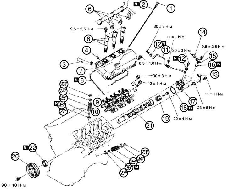


4. Remove the oil dipstick (1).

5. Remove the sealing ring (2).

6. Disconnect the hose connection (3).

7. Disconnect the positive crankcase ventilation hose connection (4).

[The article is based on data from the website MitsubishiMan.ru]

8. Disconnect the ignition coil connector (5).

9. Remove the ignition coil (6).

10. Remove the cylinder head cover (7).

11. Remove the cylinder head cover gasket (8).

12. Remove the rocker arms and shaft assembly (inlet side) (9).

13. Remove the rocker arms, shaft and hydraulic compensators as an assembly (outlet side) (10).

1) Install the special tool MD998443 as shown in the figure to prevent the hydraulic lifters from falling out.
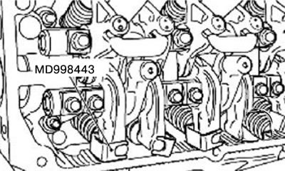


Caution: Never disassemble the rocker arm and shaft assembly.


2). Loosen the mounting bolt of the rocker arms and shaft assembly, and then remove the rocker arms and shaft assembly.

14. Remove the oil pipe (11).

15. Remove the gasket (12).

18. Remove the wiring bracket (13).

17. Disconnect the camshaft position sensor connector (14).

18. Remove the camshaft position sensor (15).

19. Remove the sealing ring (16).

20. Remove the camshaft position sensor fastener (17).

21. Remove the camshaft position sensor mounting gasket (18).

22. Remove the camshaft position sensor cylinder (19).

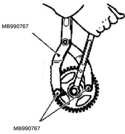
23. Remove the camshaft sprocket (20).

1) Remove the camshaft sprocket using special tools MB990767 and MD998719.


24. Remove the camshaft (21).

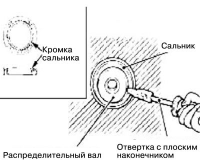
25. Remove the camshaft oil seal (22).

1). Make a cut on the edge of the seal using a knife.

Caution: Be careful not to damage the camshaft and cylinder head.


2) Insert a flat-head screwdriver into the cut on the edge of the seal and remove the seal.


26. Remove the breadcrumbs (23).


27. Remove the valve spring plate (24).

28. Remove the valve spring (25).

29. Remove the valve stem seal (26).

30. Remove the valve spring seat (27).

Model with 6G7 engine
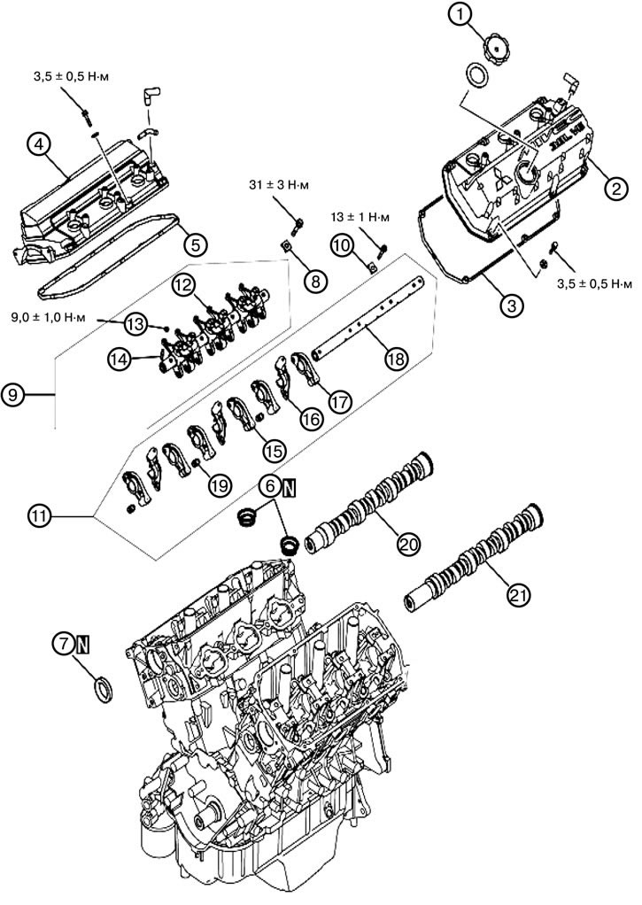


1. Remove the oil filler cap (1).

2. Remove the left cylinder head cover (2).

3. Remove the cylinder head cover gasket (3).

4. Remove the right cylinder head cover (4).

5. Remove the cylinder head cover gasket (5).

6. Remove the oil seal (6).

7. Remove the camshaft oil seal (7).

8. Remove the valve rocker shaft cover (8).

9. Remove the valve rocker shaft and valve rocker arms as an assembly (inlet side) (9).

10. Remove the valve rocker shaft cover (10).

11. Remove the valve rocker shaft and valve rocker arms as an assembly (outlet side) (11).

12. Remove the intake valve rocker arms (12).

13. Unscrew the nut (13).

14. Unscrew the adjusting screw (14).

15. Remove valve rocker arm C (15).

16. Remove the plunger lever (16).

17. Remove valve rocker arm D (17).

18. Remove the valve rocker shaft (18).

19. Remove hydraulic compensators (19).

20. Remove the right camshaft (20).

21. Remove the left camshaft (21).

Model with 4M4 engine
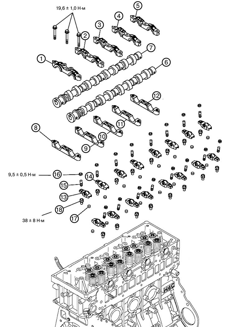


1. Remove camshaft cover No. 1 (1).


2. Remove cover No. 2 of the camshaft (2).

3. Remove cover No. 3 of the camshaft (3).

4. Remove cover No. 4 of the camshaft (4).

5. Remove cover No. 5 of the camshaft (5).

6. Remove the intake camshaft (6).

7. Remove the exhaust camshaft (7).

8. Remove camshaft fastening No. 1 (1).

9. Remove fastening No. 2 of the camshaft (2).

10. Remove fastening No. 3 of the camshaft (3).

11. Remove fastening No. 4 of the camshaft (4).

12. Remove fastening No. 5 of the camshaft (5).

13. Remove the short valve rocker arm (13).

14. Remove the long valve rocker arm (14).

15. Unscrew the adjusting screw (15).

16. Unscrew the lock nut (16).

17. Remove the valve cover (17).

18. Unscrew the bolt (18).
This article is available at: russian, bulgarian, belarusian, ukrainian, serbian, croatian, romanian, polish, slovak, hungarian
This article was reviewed by: Miroslav Rakov
Share with friends:
◀ Previous
Pajero 4: Engine repair
Next ▶

Installing the crankshaft pulley
Removal the crankshaft pulley
Removal air from hydraulic compensators
Simple check of hydraulic compensators
Checking hydraulic compensators
Installing the camshaft and camshaft seal
Removal the oil pan and oil filter
Installing the oil pan and oil filter
Removal the crankshaft seals
Installing crankshaft seals
Similar materials for other Mitsubishi models

➤ Camshaft Drive Belt — Check, Tension (SOHC, 8 and 12 Valves) Mitsubishi Colt 4 and 5 (1991-2003)
➤ Removal and installation the camshaft of a gasoline engine Mitsubishi Lancer 3 and 5 (1984-1992)
➤ Camshaft(s) — Removal, Inspection and Installation Mitsubishi Galant 5 (1983-1989, petrol)
➤ Installing the exhaust camshaft assembly Mitsubishi L200 4 (2005-2014, diesel)
➤ Removal and installation camshaft seals (4G63) Mitsubishi Outlander 1 (2003-2008)
➤ SOHC Engine Camshaft and Camshaft Seal Mitsubishi Carisma (1995-2004)
Link in different formats to this article
Comments and feedback from visitors
No comments yet


Add up two numbers 39 + 11


Pajero 4 (2006-2021) 
  • General information
  • User manual
  • Troubleshooting
  • Maintenance
  • Technical specifications
  • Power unit
  • Engine repair
  • Cooling system
  • Lubrication system
  • Fuel system
  • Engine management system
  • Intake and exhaust system
  • Engine electrical equipment
  • Transmission
  • Clutch
  • Manual gearbox
  • Automatic gearbox
  • Drive shafts
  • Chassis and running gear
  • Front suspension
  • Rear suspension
  • Brake system
  • Steering
  • Body and interior
  • Exterior (external elements)
  • Interior (internal elements)
  • Doors, locks and windows
  • Body dimensions
  • Electrical equipment
  • Safety system (SRS)
  • Air conditioner
  • Equipment and devices
  • Electrical diagrams
Pajero 1 and 2 (1982-1999) 
  • General information
  • User manual
  • Seats and seat belts
  • Instruments and controls
  • Driving and operation
  • Maintenance
  • Power unit
  • Gasoline engines
  • Diesel engines
  • Ignition system
  • Engine electrical equipment
  • Cooling and lubrication system
  • Power and exhaust system
  • Fuel system (gasoline)
  • Fuel system (diesel)
  • Transmission
  • Clutch
  • Mechanical gearbox
  • Automatic gearbox
  • Drive shafts and axles
  • Chassis and running gear
  • Front suspension
  • Rear suspension
  • Steering
  • Brake system
  • Body and interior
  • Exterior (external elements)
  • Interior (internal elements)
  • Doors, locks and windows
  • Electrical equipment
  • Equipment and devices
  • Heater and air conditioner
  • Cruise control
  • Headlights and lighting
  • Electrical circuits
MitsubishiMan.ru © 2018–2026 • Mobile version • Articles about Mitsubishi • Contacts • Sitemap: EN BG BY UA RS HR RO PL SK HU • Site search • Bookmark
Colt 2 and 3 (1983-1993) · Colt 4 and 5 (1991-2003) · Colt 5 (1995-2003) · Lancer 3 and 5 (1984-1992) · Lancer 9 (2000-2007) · Galant 5 (1983-1989) · Galant 6 and 7 (1987-1998) · L200 4 (2005-2014) · Outlander 1 (2003-2008) · Pajero 1 and 2 (1982-1999) · Pajero 4 (2006-2021) · Carisma (1995-2004) · Space Star (1998-2005) ·
This resource sets cookies 🍪 to avoid bothering you with repeated data entry.