



Contents: Removal ⤓ Installing the oil seal ⤓ Installing the valve spring ⤓ Installing crackers ⤓ Installing camshafts ⤓ Installing the camshaft oil seal ⤓ Installing the camshaft sprocket ⤓ Installing the camshaft position…⤓ Installing the camshaft position…⤓
Drain the coolant and engine oil.
Remove the air filter assembly.
Remove the ignition coils.
Remove the upper timing belt cover.
Remove the timing belt.
Removal
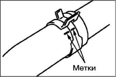
After marking the relative positions of the radiator hose and clamp, disconnect the upper radiator hose.
Secure the camshaft sprocket from turning using a special fork holder and special bolts or using a hex key on the camshafts (the cylinder head cover must be removed).
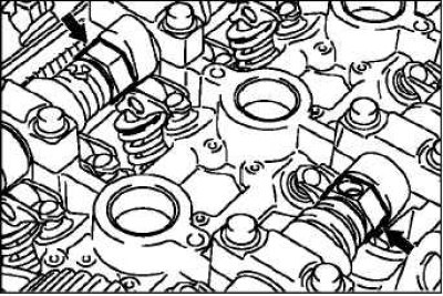 | 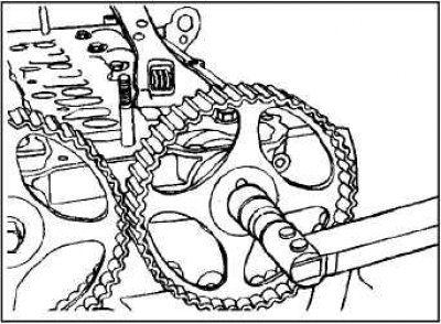 |
Loosen the camshaft sprocket mounting bolt.
Note: When disassembling the valve mechanism and dehydrating the valves, use special tool MD 998772.
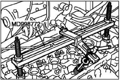
Note: When disassembling the valve mechanism and dehydrating the valves, use special tool MD 998772.
Installing the oil seal
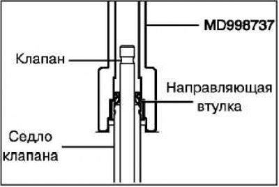
Apply a thin layer of engine oil to the lip of the oil seal. Install the oil seal by hand so that its bottom touches the top surface of the guide sleeve.
Slowly press the valve stem seal vertically until the special tool rests against the valve spring plate installed in the cylinder head.
Installing the valve spring
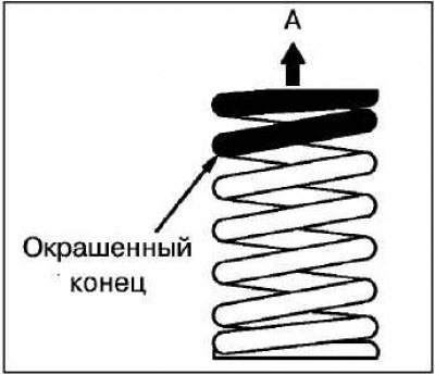
Install the valve spring with the blue painted end A facing up as shown in the figure.
Installing crackers
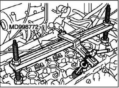
Using special tools, install the crackers as shown in the figure.
Installing camshafts
Apply a small amount of engine oil to the camshaft lobes and journals.
Install the camshaft into the cylinder head.
Caution: Be careful not to damage the camshafts during installation.
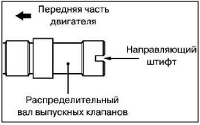
Do not mix up the camshafts. There is a hole on the end of the rear part of the exhaust camshaft for the camshaft position sensor rotor mounting bolt.
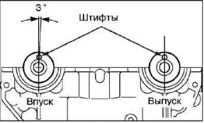
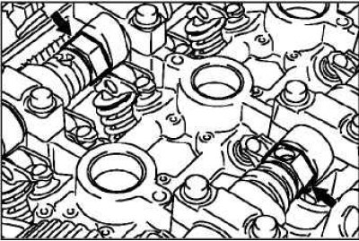
Position the camshafts in the cylinder head so that their guide pins are in the position shown in the illustration.
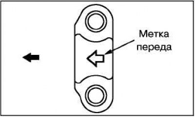
Since some bearing caps have the same diameter, to avoid confusion, check the identification marks before installing the caps.
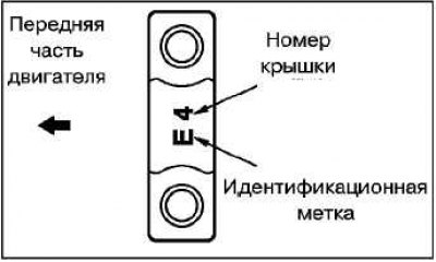
Identification marks (applied to the front cover and bearing caps No.2 – No.5).
- Inlet valve side: I.
- Exhaust valve side: E.
Apply a continuous bead of sealant approximately 3 mm in diameter to the cylinder head mating surface at the 6 points shown in the figure.

Install the camshaft bearing cap gasket onto the cylinder head.
Install the camshaft bearing cap assembly onto the cylinder head before the sealant dries and hardens.
Install the camshaft bearing cap block mounting bolts and gradually tighten the bolts in two or three steps in the order shown in the illustration. Tighten the bolts to the specified torque during the final tightening sequence.
Installing the camshaft oil seal
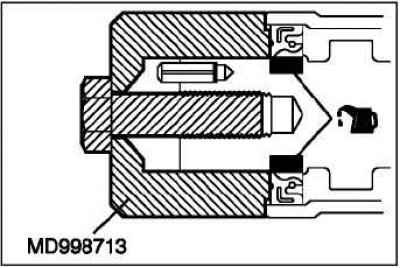
Apply a small amount of engine oil to the seal lip around its entire circumference.
Using a special mandrel, press in the seal as shown in the figure.
Install the rocker arm axles as an assembly.
Installing the camshaft sprocket
Secure the camshaft sprocket from turning using a special fork holder and special bolts or using a hex key on the camshafts (the cylinder head cover must be removed).
Tightening torque: 89±9 Nm.
Installing the camshaft position sensor support

Before installation, apply the specified sealant in a continuous bead approximately 3 mm in diameter to the camshaft position sensor support.
Installing the camshaft position sensor rotor
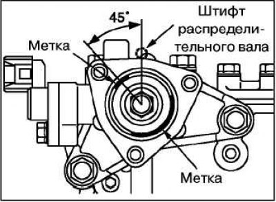
Make sure that the piston of the first cylinder is located at top dead center (TDC) (the exhaust camshaft pin is pointing vertically upwards).
Note: The camshaft may rotate under the action of the exhaust valve springs.
Install the camshaft position sensor rotor so that the white paint mark is located as shown in the figure.
When connecting the upper radiator hose, push the hose onto the pipe until it rests against the protrusion on the pipe, then tighten the clamp.
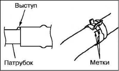
The hose clamp should always be installed in the same position as it was installed when removed. Therefore, before installing the clamp, align the alignment marks on the hose clamp and the radiator hose, then connect it.
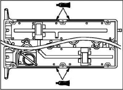
Apply beads of sealant to the four locations shown in the figure and install the cylinder head cover within 15 minutes.
Install the coolant inlet pipe and thermostat housing assembly.
Install the timing belt.
Install the upper timing belt cover.
Install the ignition coils.
Install the air filter assembly.
Adjust the timing belt tension.
Fill with coolant and engine oil.